
2012-03-20 10:13 81K 768 x 831
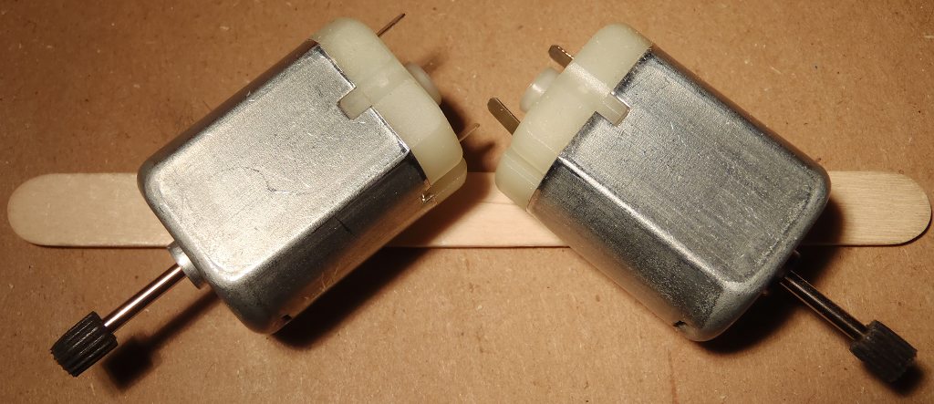
Mount wheel tube on motor axle

2012-03-20 10:20 54K 1024 x 355
Mount motors to a stick. Make sure same side of both motors are facing you.
2012-03-20 10:27 86K 1024 x 443
When glue hardens, turn over to mount other side of motor frame.

2012-03-20 10:33 58K 768 x 521
Mark stick for frame width

2012-03-20 10:43 50K 768 x 534
Glue on body stick

2012-03-20 10:50 108K 1024 x 960
Check that motors are aligned with + in the center, and robot moves forward, tadpole style

2012-03-21 08:21 75K 1024 x 523
Attach diodes to motors with stripe towards positive motor terminal
2012-03-20 10:57 102K 1024 x 680
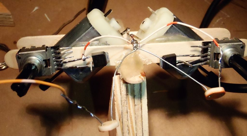
Mount the two pins on your right as you look at the curved side of a transistor in the TO92 package to the edge and sweeper pins of a 10-20K potentiometer
2012-03-20 11:04 84K 1024 x 656
Mount transistor gate and source to edge and sweeper pin of a 10K to 20K potentiomenter

2012-03-20 11:25 79K 1024 x 646
Attach wire connecting positive terminals of motors and one leg of the CdS cells
2012-03-20 11:28 80K 1024 x 562
Wire other side of CdS cell to gate of opposite side transistor.

2012-03-20 11:31 91K 1024 x 564
Gate on power MOSFET packages is usually on the left when reading the markings.

2012-03-20 11:34 51K 768 x 457
Gate on other side. In this case, one pin is missing from potentiometer, so I had to use alternate pins on this double potentiometer.

2012-03-20 11:37 110K 1280 x 654
Solder wires to drain of transistors

2012-03-20 11:41 74K 1024 x 652
Wire transistor drains to corresponding motor "minus" tabs

2012-03-20 11:44 50K 768 x 426
Wire Source's to ground. Note than when wiring to al already soldered connection, attaching an alagator clip can protect existing joing from heat of new solder connection.

2012-03-20 11:47 83K 1024 x 480
Connect Source on both transistors, they will both be connected to the ground (minus) of the battery.

2012-03-21 08:08 69K 1024 x 393
Connect battery minus (ground) wire to one of the transistor source pins. This pin should also be connected to the other transistor source to form the ground bus.

2012-03-21 08:11 60K 768 x 647
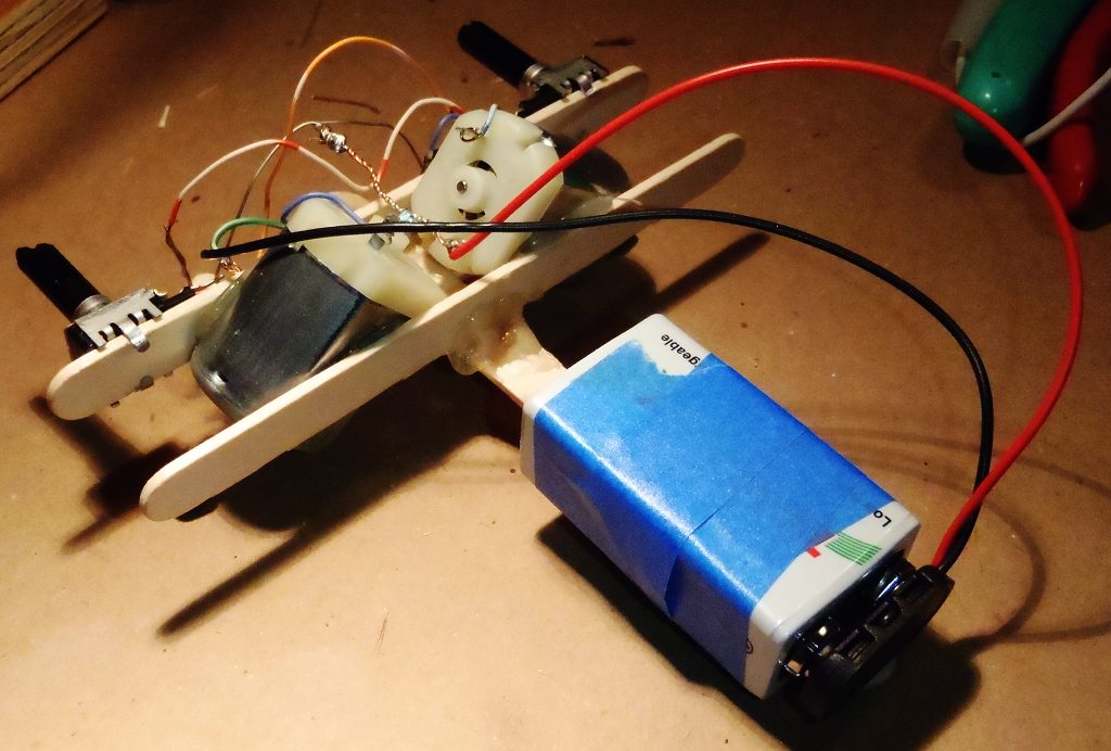
Connect the battery plus wire to the positive terminals on the motors.
2012-03-21 08:14 104K 1024 x 692
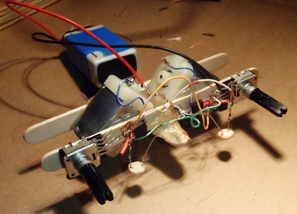
Battery can now be connected.
2012-03-21 08:18 111K 1024 x 741
Adjust sensor positions to point towards the expected position of the guiding light source.