| Select matching CdS cells
|
Measure the resistance of cell in dim, ambient light.
Repeat this measurement pointing toward a lamp.
The second measurement should be significantly lower.
Repeat this measurement on several cells until you find two which
have similar values both under dim light and when pointed toward a lamp.
|
| Mount Wheels on motor axles
|

|
|
Place motors on table in a position similar to where they will be in the final robot, with the same side of each motor facing you. Lay the diodes on the motors such that the stripe is towards the inside. Solder the diodes in place.
|

|
| Power up each motor by placing the + lead on a battery on the motor tab toward the stripe on the diode, and the - lead on the other side of the diode. Make sure that one motor spins clockwise, and the other motor spins counter-clockwise. If this is not the case, reverse one of the diodes.
|
|
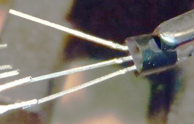
| Locate the drain pin on two transistors, and bend it away from the other two pins.
|
|
| Strip about 3mm from the ends of 4 wires. The wires should be at least 5cm long each. Bend the stripped end of each of these wires into a small hook.
|

|
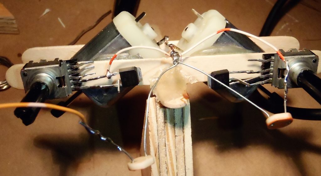
| Arrange the potentiometers as they will be mounted on the robot. One on the left, one on the right, facing forward.
|
Photo is shown after mounting to frame, but solder the transistors to the pots like this, with the wires attached before mounting.
It is much easier to do this soldering before mounting on the frame.

|
| Arrange the transistors so that the gate and source pin are aligned with an edge and sweeper pin on each of the potentiometers. It will be desirable for the bent drain pin to point up (or forward) in this arrangement on the constructed robot.
|
| Hold the source pin of a transistor to the desired pin of the potentiometer, and help hold it in place with the hook of one of the wires. Solder this 3-way connection together.
|

|
| In a similar manner, solder the gate pin to the corresponding leg of the potentiometer with a wire hook.
It is best for the wires to head in opposite direction from these solder joints so that they are not likely to short when the robot bumps into things.
|
| Place both motors in their desired relative locations on the finished robot, with the tab attached toward the striped end of the diode towards the center.
|

|
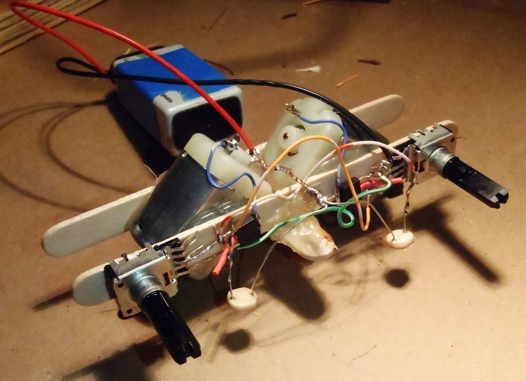
| Put a generous dab of hot glue on each motor, and attach one side of the popsicle stick frame. You will have a few seconds to adjust the alignment before the glue cools. When the parts are aligned, wait for the glue to harden.
|
|
| Flip the motor assembly over, and glue another craft stick to the other sides of the motors for added strength.
|
| Place the wheels of the motor assembly on the table and attach the + end of a battery to the motor tab attached to the striped end of one of the diodes. Attach a lead from the - side of the battery to the other side of the same diode. The motor assembly should try to drive away. Note which direction it drives. Place an X on the stick that the motor tries to drive away from.
|


|
| Repeat for the second motor, making sure that both motors try to drive the frame in the same direction.
Place an X marking the stick which will be the backward facing side of the frame.
The pots and sensors will be attached to the other, frontward facing side of the frame.
|
| Place the third craft stick where you will want it on the final robot. This stick usually forms a tail where the battery will be mounted, so most of the stick will extend out from the X side of the motor frame. Mark the desired locations on this stick where the motor frame sticks will cross.
|
|
| Put a dab of hot glue on each of these lines, then balance the motor frame assembly on the third stick, in the pools of hot glue. You have a few seconds to check the balance and alignment of this stick to the frame before the glue begins to harden.
|

|
| When aligned, wait for the glue to harden.
|
| Hold the robot tail down on the table.
|
|
| Place some hot glue on the forward facing side of the motor frame, and mount one of the potentiometer assemblies. Be careful that the placement of the hot glue does not interfere with the motion of the potentiometer adjustments.
|
|
| Repeat for the other potentiometer assembly
|
Solder the bent drain pin on the transistors to the motor diode lead away from the stripe on it's corresponding motor.
If the two leads cannot reach,
or cannot be connected without risk of shorting other leads,
use a small length of insulated wire to make the connection.
|

|
| Repeat for the other NON-stripe motor-diode lead to the corresponding bent transistor drain pin.
|
| Solder the diode leads towards the stripe on the motors together, and solder them to one side of the CdS sensors. If the leads are not long enough to place the sensors where you want, use an uninsulated wire to connect the stripe end of the diode leads together and extend forward to the location where you wish to the one lead from each of the sensors.
|

|
| Solder the wire to the gate pin of one transistor (center pin on TO-92 package) to the other lead of the sensor on the opposite side. Repeat for both sides. This is a criss-cross connection where each motor/transistor/potentiometer assembly is attached to the sensor on the opposite side.
|
|
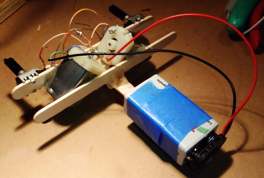
| Solder the positive battery terminal wire (red) to a diode lead toward the striped side of the diode.
|

|
| Take the remaining source wires that were soldered to the transistors, and solder them together with the minus (black) lead on the battery connector.
|

|
| Plug in battery and test.
|
|
| Adjust pointing direction of sensors, and sensitivity.
|
|
 This is the circuit diagram for the light sensitive motor driver.
The light sensor for the right motor is on the left,
and the light sensor for the left motor is on the right.
The sensors are cross-wired to the opposite motor's transistor gate.
This is the circuit diagram for the light sensitive motor driver.
The light sensor for the right motor is on the left,
and the light sensor for the left motor is on the right.
The sensors are cross-wired to the opposite motor's transistor gate.