Pages: 1 [2]
 ReplyUnsubscribeRSS feedStickyClose   
Author Topic: Dalek
adric
Administrator
Posts: 178
Permalink
Post Re: Dalek
on: October 30, 2012, 09:24
Quote RemoveEdit

Back on the subject of building a body (possibly one of a few), I was reading this article about an insane AT-ST Walker (star wars), and i liked some of his light weight fabrication techniques.

http://www.cockeyed.com/incredible/atst_costume/atst_costume1.html

-Quelab, Come make something!

Mr.What
Administrator
Posts: 197
Permalink
Post Initial platform constructed
on: November 4, 2012, 10:53
Quote RemoveEdit

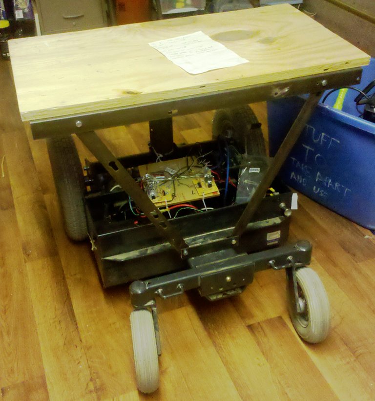
Platform top is 29.25" wide (barely fits through doors), 16" deep. The metal frame is a little deeper, for about 16.5" total platform depth.

The rear wheels are only 25" wide, so I have an overhang of about 2.5" on each side. We will most likely want to cut this down so it can fit through common 29" (30" minus moulding...) doors.

The front brace extends 4" in front of the frame, but when the casters are out front (like when going backwards) they extend 8" past the front of the frame. The rear wheels extend 9" behind the frame back.

The main platform is 25.75" above the floor.

Image

We could lower the platform, but if we do, we'll need to make it removable, so that we can service the electronics and batteries. With the current high platform, we can get to electronics and batteries without disassembling the platform.

I like the idea of Chloroplast construction. I have used this stuff before. We should look for a proper plastic welder, since it can be tricky to glue.

We may want to skip some balls near the floor, at least around the rear wheels. They are 25" apart, which will be a min of 27" with a body around them (will trim down the platform top). I wouldn't want to go much wider for the door issue. If we skip some side balls, or make them flatter we should be able to clear doorways.

How much support frame would chloroplast need, and how might we attach it to the platform?

adric
Administrator
Posts: 178
Permalink
Post Re: Dalek
on: November 4, 2012, 12:11
Quote RemoveEdit

it does not need much, its like light cardboard, but that being said, i think the next step would be to build the head/turret, because the rest of it could pretty much hang from the "shoulders" of that.

but to do any of the layout/design i think we really need to clean up the lab! with my arthritis i dont have the stamina or the energy or the desire to do it all. so we will see if we get volunteers to help sunday.

-Quelab, Come make something!

Mr.What
Administrator
Posts: 197
Permalink
Post Neural Network drive
on: November 30, 2012, 14:56
Quote RemoveEdit

It might actually be easier, given my skillset, to build a neural network brain for moving the dalek. Put several ping sensors around the dalek. Build a network that takes in ping sensor readings, and outputs motor drive commands. (Perhaps also a buzzer, light, etc. output neuron later).

We can make full autonomous later, but at first talk to a laptop via bluetooth. Send sensor readings to laptop, laptop runs NN, and sends motor commands back, via serial-over-bluetooth.

To train the network, write a simulation of robot and sensor. Set up a little virtual world. (A simple drawing of a room, with obsticles). Drive the robot around as you want it to behave, back-prop those motor commands through the net.

When it can run OK, mostly autonomous, move to the real robot. Train some more. (Drive around, and back-prop commands through the net). That will handle any difference between real and simulated sensors, and tweak the net.

Then, when running, have override mode on the laptop. When the robot gets "naughty", send correction commands, and back-prop (train) the net on those corrections, too.

The more we use the robot, the better it will get at randomly walking about, avoiding collisions, and chasing things.

This will take some 6-12 ping sensors on the robot, some communication code to get sensors/commands over bluetooth, then use some neural net software we already have to configure and train the net.

Totally achievable, and could be a great attention getter.

Commercialization potential... we could have it work with Lego mindstorms, or produce robot kits, and sell NN training software (in Java, cross-platform).

People might enjoy trying to train different behaviors (chasing, encouraging collision, avoiding collision, avoiding all neighbors...) and let swarms go.

----

We could also command and get sensor readings over a WiFi server on the robot arduino. Here's a swell example controlling an RC car over WiFi using an arduino. I don't think we need a custom shield. We can use a standard WiFi shield, then wire up sensors and motor drivers as desired.

http://www.instructables.com/id/How-to-build-an-Arduino-WiFi-4x4-with-Android-Cont

Since ideas for this project are growing rapidly, I think I may move over to a mega.

adric
Administrator
Posts: 178
Permalink
Post Re: Dalek
on: December 1, 2012, 17:23
Quote RemoveEdit

what about going higher tech, than ultrasonics sensors, (although i have seen you can buy ultrasonic parking assist kits pretty cheap these days, with 4-5 sensors. What about going with a microsoft kinect based vision system? i think walter even bought the lab one to play with. would probably need some more beefy hw to run, but i suspect so would your neural net.

-Quelab, Come make something!

Mr.What
Administrator
Posts: 197
Permalink
Post kinnect
on: December 4, 2012, 15:35
Quote RemoveEdit

The neural net is not too bad. For now, it's java, so Android is fine. A phone or tablet. Certainly a laptop. Kinect is not out of the question. I don't know a lot about their interface. Kinect is likely in netbook/raspbery-pi area. We may need several of them and/or mount on a servo to scan. Either way, sonar is a good idea as an avoid-bump detector... but we may not need as many sensors with a Kinect or two.

The neural net is rather small and simple. A few hundred lines of code. A couple thousand at most. Not a ton of memory. (say 3-ish 40x40ish matrices. that's it.) Training the net is a larger app, but still not huge. The net could easily run self-contained (coded in C) on a larger MCU, easily on one of the ARM based ones.

Kinnect is MUCH higher complexity, but would much more detailed. Much fewer blind spots. (Full 2D coverage in one direction)

adric
Administrator
Posts: 178
Permalink
Post Re: Dalek
on: December 6, 2012, 10:11
Quote RemoveEdit

Indeed, i think one would work for most stuff, and maybe would be able to be tapped as a webcam too.
http://jonmacey.blogspot.com/2012/07/raspberry-pi-and-kinect.html

also caught this ting on using a vibrating motor to improve the data quality of the kinect

http://hackaday.com/2012/08/13/building-a-better-kinect-with-a-pager-motor/

-Quelab, Come make something!

Mr.What
Administrator
Posts: 197
Permalink
Post sonar test
on: December 23, 2012, 13:14
Quote RemoveEdit

Here is a sketch to test sonar modules.

pulseIn polls, but queries registers directly, and computes its own time by counting instructions, and knowing how many clock cycles it takes to do those instructions. So it is a more accurate poll.

I included a version that uses an interrupt. The Arduino Mega has 6 interrupts. However, I am reluctant to use ALL of them for the sonars,
so I might try to do 3 at a time, and multiplex the echo pins back.

// settings for mega testing an HC-SFR0 sonar
//
// when user sends a character over serial, report range timings

#define PIN_TRIGGER 31
#define PIN_ECHO 2   // use pin 2, same on mega and uno, interrupt 0
#define EVENT_QUEUE_DEPTH 8

//#define INLINE_POLL
#define USE_INTERRUPT

#ifdef  USE_INTERRUPT
struct {
  unsigned long start, ping, echo;  // time of ping and echo, us
} Sonar;
#endif

void setup()
{
  pinMode(PIN_TRIGGER,OUTPUT);
  pinMode(PIN_ECHO,INPUT);
  digitalWrite(PIN_TRIGGER,LOW);
#ifdef USE_INTERRUPT
  Sonar.ping = Sonar.echo = 0;
  attachInterrupt(0,echoReceived,FALLING);
#endif
  Serial.begin(9600);
}

void echoReceived()
{
  Sonar.echo = micros();
}

#define SPEED_OF_SOUND 34000   // cm/s
unsigned int sonarTime2cm(unsigned int sonarPulse_us)
{
  // there is an unaccounted for bias in time return, re-cal for each version
#ifdef INLINE_POLL
#else
  return((sonarPulse_us-0)/58);
#endif
}

long nPulses = 0;

// This is very simple, and shows how sonar works, but is not terribly
// accurate or efficient.  digitalRead() takes about 6 us,
// which limits accuracy, and as a poll, it does lock the MCU
// until timeout.
//
// Returns time from falling edge of trigger, to falling edge of echo pulse
unsigned int sonarPoll(int pinTrigger, int pinEcho)
{
  digitalWrite(pinTrigger,HIGH);
  unsigned long t0 = micros();
  delayMicroseconds(6);  // whole pulse must be at least 10us, but delay can be less because of overhead
  digitalWrite(pinTrigger,LOW);
  unsigned long t1 = micros();
#ifdef INLINE_POLL
  // simple, in-line poll
  unsigned int timeout = 0;
  unsigned long t2 = 0;
  unsigned long t3 = 0;
  //delay(1);//Microseconds(500);
  while (timeout++ < 60000)
  {
    if (digitalRead(PIN_ECHO) == HIGH)
    {
      t2 = micros();
      while (timeout++ < 60000)
      {
        if (digitalRead(PIN_ECHO) == LOW)
        {
          t3 = micros();
          break;
        }
      }
    }
  }
  unsigned long dt = t3-t2;
  if (t2==0) t2 = micros();
  if (t3==0) t3 = micros();
#else
  // use Arduino.h pulseIn() which polls registers directly, more accurate
  unsigned long dt = pulseIn(pinEcho,HIGH,100000);
#endif
  
  nPulses++;
  Serial.println();
  Serial.print(t0);
#ifdef INLINE_POLL
  Serial.print(',');Serial.print(t2-t0);Serial.print(',');Serial.print(t3-t0);
#endif
  Serial.print(F("\t"));
  Serial.print(nPulses);
  Serial.print(F(")\t"));
  Serial.print(t1-t0);
  Serial.print(F("\t"));
  Serial.print(dt);
  Serial.println();
  if (dt > 0xffff) dt = 0xffff;
  return((unsigned int)dt);
}

void sendPing()
{
  digitalWrite(PIN_TRIGGER,HIGH);
  Sonar.start = micros();
  delayMicroseconds(6);  // whole pulse must be at least 10us, but delay can be less because of overhead
  digitalWrite(PIN_TRIGGER,LOW);
  Sonar.ping = micros();
  nPulses++;
  Sonar.echo = 0;
}
unsigned int retrievePulseTime()  // retrieve sing-around time, us
{
  long dt = Sonar.echo - Sonar.ping - 464;  // bias of time from falling edge of trigger to rising edge of return signal
  if (dt > 0xffff) dt = 0xffff;

  Serial.println();
  Serial.print(Sonar.start);
  Serial.print(',');Serial.print(Sonar.ping-Sonar.start);
  Serial.print(F("\t"));
  Serial.print(nPulses);
  Serial.print(F(")\t"));
  Serial.println(Sonar.echo-Sonar.ping);
  //Serial.print(F("\t"));
  //Serial.print(dt);
  //Serial.println();
 
  Sonar.echo = Sonar.ping = 0; // clear sonar
  return((unsigned int)dt);
}

void loop()
{
  unsigned int pulseTime_us;
  
#ifdef USE_INTERRUPT
  if (Sonar.echo)
    { // echo received
      pulseTime_us = retrievePulseTime();
    }
  else
    {
      if (Sonar.ping)
        { // waiting for echo
          unsigned long t = micros();
          if (t > Sonar.ping + 0xfff0) Sonar.echo = t; // timeout
        }
      else if (Serial.read() > 0)
        { // start next pulse
          sendPing();
        }
      return;
    }
#else
  if (Serial.read() < 0) return;  // no update command
  pulseTime_us = sonarPoll(PIN_TRIGGER, PIN_ECHO);
#endif
  int cm = sonarTime2cm(pulseTime_us);
  Serial.println(cm);
}
Mr.What
Administrator
Posts: 197
Permalink
Post More sonar demos
on: December 23, 2012, 18:11
Quote RemoveEdit

Have altered the above to trigger two sonar sensors simultaneously. Their trigger signals are connected to pins with external interrupts. The mega has external interrupts on pins 2,3 (which are also PWM), and 18-21, which clobbers the use of two of the serial pins. That leaves 3 hardware serials left, pin 0,1 and 14-17. Need to look at where the mega timers are to decide which pins to use for the motor drivers.

I will need two PWM pins for motor drivers, and I may wish to mess with the timer settings to alter the PWM period. We need to keep in mind which timers are used for the servo library, which we may want someday to scan the sonars and/or radio tracker.

I could use all 6 pins for sonar interrupts, eating up all of my external interrupt ports.... if I need more interrupts, we'll need to multiplex the sonar pins, doing 3 soundings simultaneously, and ping-pong the sonar samples.

May want 1 timer for sensor sample heartbeat.

Timer 0 is usually for time.
Timer 1 is usually for the servo library.

Timer 2,3,4,5 are all OK to use for other things on mega.
(3,4,5 are mega only)

Timer Pins
0 (time) 5,6 | uno
1 (servo)9,10 | uno
2 11,3 | uno

0 4,13
1 11,12
2 9,10
3 2,3,5
4 6,7,8
5 45,45,44 ??? (my board marks 3..13 as PWM)

Mr.What
Administrator
Posts: 197
Permalink
Post 433 MHz, 3-element Yagi design
on: December 25, 2012, 10:29
Quote RemoveEdit

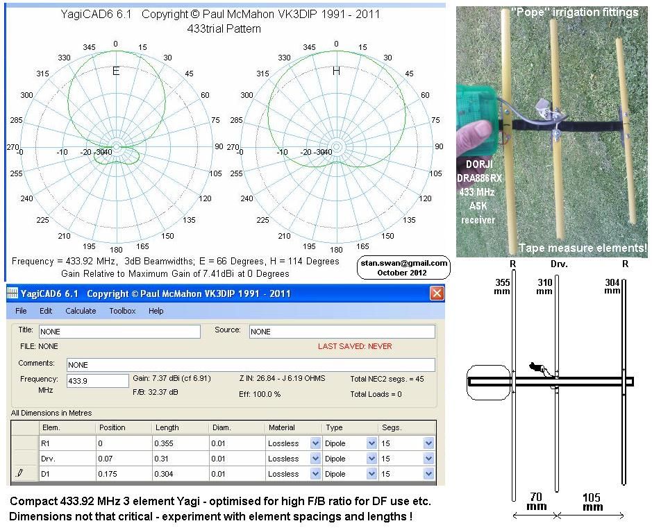
Here's a 433 MHz, 3-element Yagi antenna design, used for direction finding. I plan to start with this, but try to build it using coat-hangers (or heavy copper wires) in a chloroplast sheet.

Image

Mr.What
Administrator
Posts: 197
Permalink
Post chloroplast yagi
on: December 26, 2012, 16:04
Quote RemoveEdit

Got some chloroplast (corrugated plastic). the "4mm" thick sheet seems to have sections 5.1mm apart. (likely actually 0.20 inches) The YagiCAD program optimizes one parameter at a time, so I think I can set the spacings at multiples of 5.1mm, then optimize element lengths for a good pattern. The Plastic Supplies around Princeton and Candalaria has it for $12 for a 4x8' sheet.

BTW: Adric -- I got a 4x8 sheet of .020 mil vacuform plastic for $9

Mr.What
Administrator
Posts: 197
Permalink
Post Arduino Mega pin-change interrupts
on: January 6, 2013, 11:13
Quote RemoveEdit

Collecting info for pin-change interrupts on Arduino Mega boards has been tricky. Here's a summary.

  • Lower 3 bits of PCICR enable PC interrupts pin controlled by PCMSK2,1,0 registers, respectively. (Set bit 2,1,0 to use PC interrupts on one of these sets of pins)
  • PCMSK2 has pin-change interrupt enable flags for AVR pins PCINT23..16 respectively.
  • PCMSK1 has pin-change interrupt enable flags for AVR pins PCINT15..8 respectively.
  • PCMSK0 has pin-change interrupt enable flags for AVR pins PCINT7..0 respectively.

The AVR pins correspond to the following Arduino Mega board pins:

PCINT23  Analog15             group PCI2
PCINT22  Analog14
PCINT21  Analog13
PCINT20  Analog12
PCINT19  Analog11
PCINT18  Analog10
PCINT17  Analog9
PCINT16  Analog8

PCINT15  N/A                  group PCI1
PCINT14  N/A
PCINT13  N/A
PCINT12  N/A
PCINT11  N/A
PCINT10  DIO 14
PCINT9   DIO 15
PCINT8   DIO 0

PCINT7   DIO 13            group PCI0
PCINT6   DIO 12
PCINT5   DIO 11
PCINT4   DIO 10
PCINT3   DIO 50
PCINT2   DIO 51
PCINT1   DIO 52
PCINT0   DIO 53

I will try to start with the less used pins 50..53 for the sonar interrupts.

I think code to enable is

PCICR  |= 1;  // enable PCI0 pin group interrupt
PCMSK0 |= 0xf; // enable PC interrupts on arduino pins 50..53
...
ISR(PCINT0_vect) {
  // check which pin fell here, and note time
}
adric
Administrator
Posts: 178
Permalink
Post Re: Dalek
on: January 7, 2013, 10:46
Quote RemoveEdit

Speaking of tracking based on bluetooth. i funded a kickstarter, in a few months i may get 2 "StickNFind bluetooth chits. Might be cool for something like this. http://www.indiegogo.com/sticknfind/x/179790?c=home

-Quelab, Come make something!

Mr.What
Administrator
Posts: 197
Permalink
Post Pin-Change interrupt example on Arduno (mega)
on: January 7, 2013, 14:26
Quote RemoveEdit

Got test code running using pin-change interrupts to get sonar timings. I had a lot of trouble with pin-change interrupt documentation, and the libraries available are EXTREMELY complicated (IMOHO), just to avoid learning how to bang a few bits in a register. Here is my test driver for posterity.

// settings for mega testing an HC-SFR0 sonar
//
// when user sends a character over serial, report range timings
//
// This version tries to use Pin-Change interrupts to get sonar timings

#define PIN_TRIGGER 31
#define PIN_ECHO0 50
#define PIN_ECHO1 51
#define PIN_ECHO2 52
#define PIN_ECHO3 53

#define NUM_SONAR_SENSORS 2  // assume starting pins 50-53, then 13..10
#define TIMEOUT_US 30000
//----------------------------------------------- SonarState
const char TAB = 't';

class SonarState {
public:
  byte pinEcho[NUM_SONAR_SENSORS], nDone;
  bool done;
  int dt[NUM_SONAR_SENSORS];
  unsigned long ping, start;
  long nPulses;

  void begin()
  {
    start = ping = 0;
    dt[0]=dt[1]=0;
    pinEcho[0]=PIN_ECHO0;
    pinEcho[1]=PIN_ECHO1;
    nPulses = 0;
    nDone = 0;
    done = false;

    pinMode(PIN_TRIGGER,OUTPUT);
    pinMode(PIN_ECHO1,INPUT);
    pinMode(PIN_ECHO0,INPUT);
    digitalWrite(PIN_TRIGGER,LOW);

    PCMSK0 |= 0b1100; // enable PC interrupts on arduino pins 50,51
  }

  void sendPing()
  {
    digitalWrite(PIN_TRIGGER,HIGH);
    start = micros();
    nPulses++;
    dt[0] = dt[1] = 0;
    nDone = 0;
    done = false;
    delayMicroseconds(2);  // whole pulse must be at least 10us, but delay can be less because of overhead and above code
    digitalWrite(PIN_TRIGGER,LOW);
    ping = micros();

    // consider a delay here, to allow echo pins to go high?
    PCICR  |= 1;  // enable PCI0 pin group interrupt
  }

  // too much time passed.  reset even if not done, and set timeout vals
  void timeout(int longTime)
  {
    PCICR  &= 0xfe;  // disable PCI0 pin group interrupt
    done = true;
    nDone = NUM_SONAR_SENSORS;
    for (int i=0; i < NUM_SONAR_SENSORS; i++)
      if (dt[i] == 0) dt[i] = longTime;
  }

  /// blocks until reading is complete
  void getReadingBLOCK()
  {
    sendPing();
    int et;
    do {
      et = (int)(micros() - ping);
    } while ((!done) && (et < TIMEOUT_US));
    if (!done) timeout(et);
  }

  // convert current dt[idx] to cm
  int cm(byte idx)
  {
    int t = dt[idx];
    if ((t<=0)||(t>=TIMEOUT_US)) return(9999);
    return( (int)((t-464)/58) );
  }

  /// diagnostic method to do a sonar reading, and print results
  void printReading()
  {
    getReadingBLOCK();

    Serial.print(nPulses); Serial.print(") ");
    Serial.print(start);  Serial.print(TAB);
    Serial.print(ping-start);
    for (int i=0; i < NUM_SONAR_SENSORS; i++)
      {
        Serial.print(TAB); Serial.print(dt[i]);
        Serial.print("(");Serial.print(cm(i));Serial.print(")");
      }
    Serial.println();
  }

} Sonar;

//------------------------------------------ setup/loop
void setup()
{
  cli();  // disable interrupts
  Sonar.begin();
  sei();  // enable interrupts?
  Serial.begin(9600);
}

/// Pin-Change interrupt, for arduino pins 50..53, and 13..10
ISR(PCINT0_vect) {
  unsigned long t = micros();
  int dt = t - Sonar.ping;

  // It has been measured as taking 464us from falling edge of trigger
  // to rising edge of echo duration pulse
  if (dt < 470) return;  // still waiting for leading edge

  // check which pin fell here, and note time
  Sonar.nDone = 0;
  for (int i=0; i < NUM_SONAR_SENSORS; i++)
    {
      if (Sonar.dt[i] == 0)
        {
          if (digitalRead(Sonar.pinEcho[i]) == LOW)
            {
              Sonar.dt[i] = dt;
              Sonar.nDone++;
            }
        }
      else Sonar.nDone++;
    }
  if (Sonar.nDone == NUM_SONAR_SENSORS)
    {
      Sonar.done = true;
      PCICR  &= 0xfe;  // disable PCI0 pin group interrupt
    }
}


void loop()
{
  if (Serial.read() < 0) return;  // no update command
  Sonar.printReading();
}
Mr.What
Administrator
Posts: 197
Permalink
Post Dalek Bluetooth as beacon
on: January 7, 2013, 14:33
Quote RemoveEdit

Quote from adric on January 7, 2013, 10:46
Speaking of tracking based on bluetooth. i funded a kickstarter, in a few months i may get 2 "StickNFind bluetooth chits. Might be cool for something like this. http://www.indiegogo.com/sticknfind/x/179790?c=home

It looks to me like this could solve the beacon problem.

However, it seems that all he gets on Android is a signal strength. We'd need to write some sort of a search algorithm to random walk around, and try to drift in a direction which increases signal strength.

Tricky, but might be worth a try.

It appears that reading signal strength might be tricky, and might not even work with an active connection: http://stackoverflow.com/questions/2149295/android-2-1-how-do-i-poll-the-rssi-value-of-an-existing-bluetooth-connection

adric
Administrator
Posts: 178
Permalink
Post Re: Dalek
on: January 15, 2013, 14:06
Quote RemoveEdit

will your ultrasonic sensors work through a vinyl? http://www.thinkgeek.com/product/efa2/

-Quelab, Come make something!

Mr.What
Administrator
Posts: 197
Permalink
Post Controller re-build on Arduino Mega
on: January 17, 2013, 10:21
Quote RemoveEdit

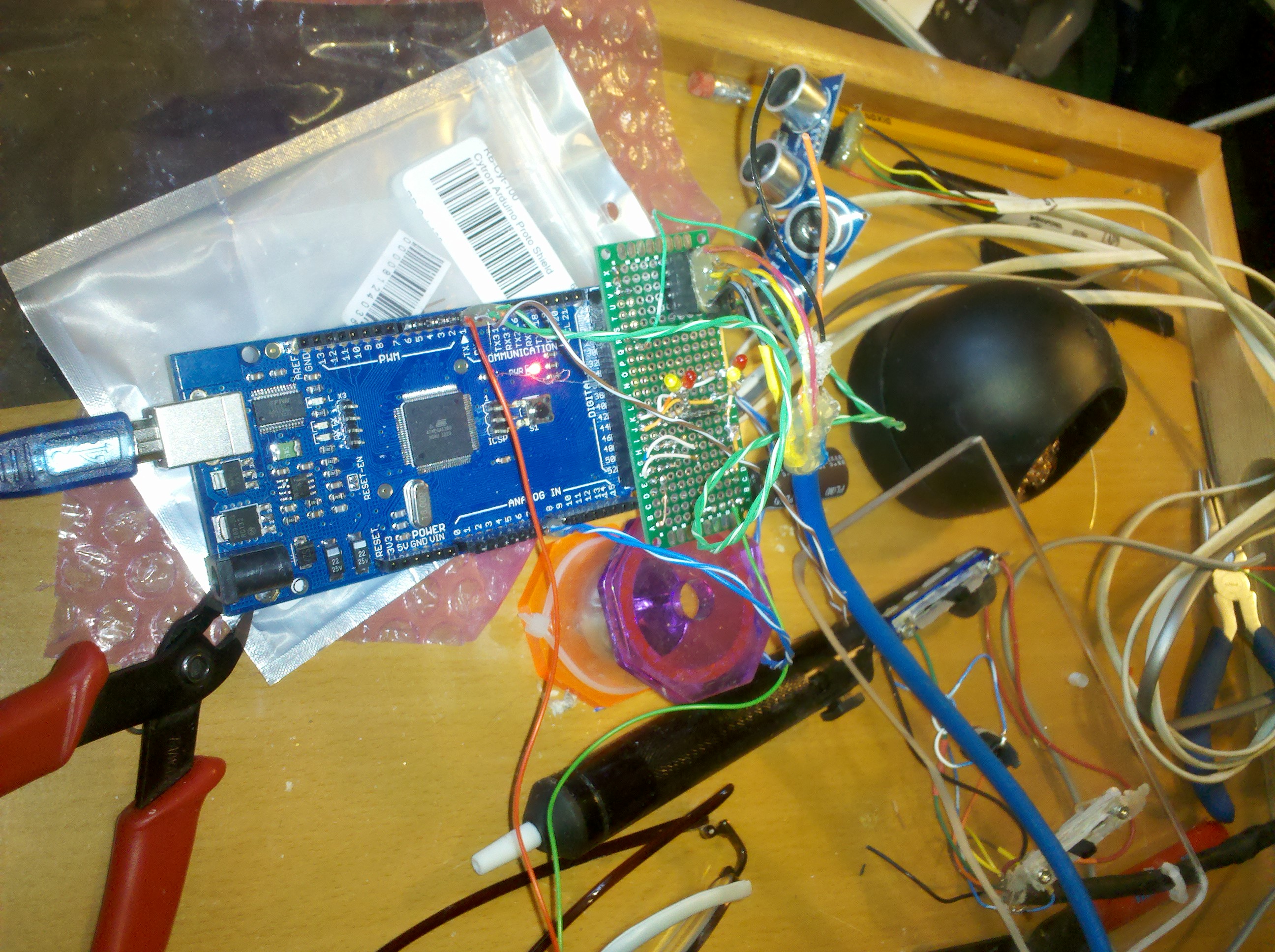
Re-built the Dalek controller on an Arduino Mega.
Now has 4 sonars, and some diagnostic LED's to show motor command levels.

Added an additional "deadman" to enable autonomous mode, while testing.

http://youtu.be/INM2M25lFi4

New code seems to be displaying reasonable sonar readings, and manual override does seem to control motor speed LEDs as expected.
Image

Mr.What
Administrator
Posts: 197
Permalink
Post Bluetooth setup
on: January 18, 2013, 11:08
Quote RemoveEdit

Got JY-MCU bluetooth module configured. It was tricky. Just plugging in, only AT+NAMEdavros worked. (Change device name to "davros"). I could not change baud rate (or PIN).

I attached the 5v line to the un-attached pad named "key". I believe that this pad is connected to inner module pin 34, which is labeled "key" on some datasheets. This should allow full AT command set.

This may not have been enough. The next thing I did was turn off transmission of EOLN characters. Then I started getting OK from my bare AT command. I was able to set baud rate to 115200 <AT+BAUD8>. This is as high as I dare go, since some devices will not do serial above 115200.

It seems to be running now, at 115200 baud, BT device name "davros"

IMPORTANT: turn off sending of EOLN characters when attempting AT commands on these bluetooth modules! (may want to pull-up "key" also)

Mr.What
Administrator
Posts: 197
Permalink
Post Catch diodes on MOSFET motor drivers
on: January 26, 2013, 10:17
Quote RemoveEdit

Sometimes, (but not always) the internal diode of a MOSFET is sufficient as a catch diode in an H-Bridge.

This article covers how to tell when this might not be the case, and an external catch diode should be added:

http://modularcircuits.tantosonline.com/blog/articles/h-bridge-secrets/mosfets-and-catch-diodes/

I'm not sure where I fall for the Dalek. If we ever do a PCB for the opto-isolated power H-bridge, I will certainly add traces for external catch diodes.

Mr.What
Administrator
Posts: 197
Permalink
Post Videos of initial autonomous collision-avoidance tests
on: February 19, 2013, 08:42
Quote RemoveEdit

http://www.youtube.com/watch?v=9Mz-5n5gWAU
http://www.youtube.com/watch?v=sknefh07KEM

Worked pretty well for a glancing collision, but still needs some work for full-speed, head-on.

Mr.What
Administrator
Posts: 197
Permalink
Post opto-isolated high-power H-Bridge
on: March 27, 2013, 12:52
Quote RemoveEdit

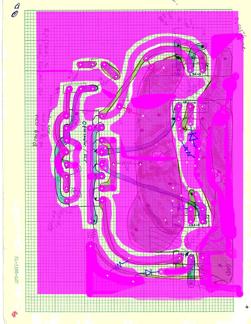
I have other drawings of this circuit, but here is work toward etching a PCB for it. I have the original drawing, with the copper-clad layout in pink, and the mask for etching I generated from it.
Image

Mr.What
Administrator
Posts: 197
Permalink
Post h-bridge drawing
on: March 27, 2013, 12:55
Quote RemoveEdit

here's the circuit layout drawing where I drew the mask in pink.
Image

Mr.What
Administrator
Posts: 197
Permalink
Post H-bridge, top mask
on: March 28, 2013, 09:43
Quote RemoveEdit

600dpi drawing of top-surface mask for H-bridge, with component guides
Image

Mr.What
Administrator
Posts: 197
Permalink
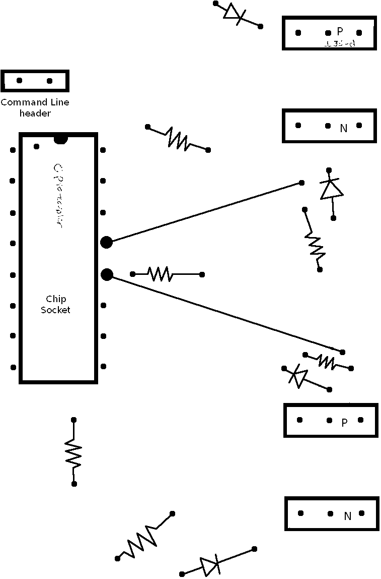
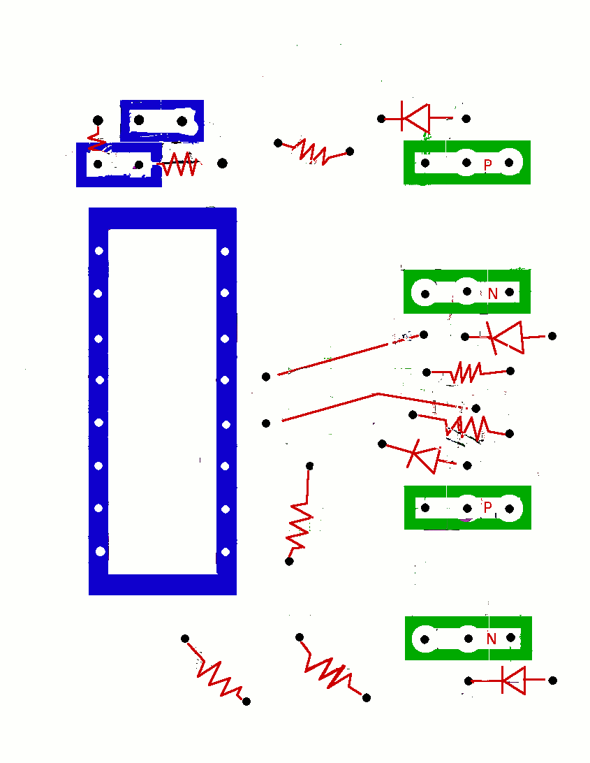
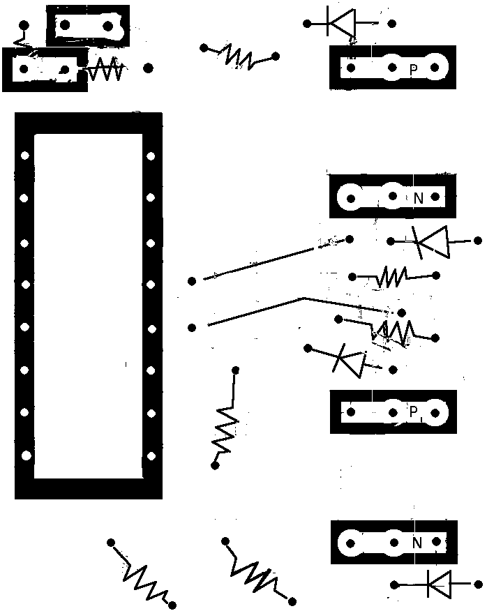
Post Smaller H-bridge masks
on: March 30, 2013, 08:05
Quote RemoveEdit

Re-drew the H-Bridge layout, making it a bit more compact
Image
Image
Image

Quick Reply:

Pages: 1 [2]
 ReplyUnsubscribeRSS feedStickyClose   
Mingle Forum by cartpauj
Version: 1.0.34 ; Page loaded in: 0.076 seconds.

[Edit Page]
 

Comments are closed.