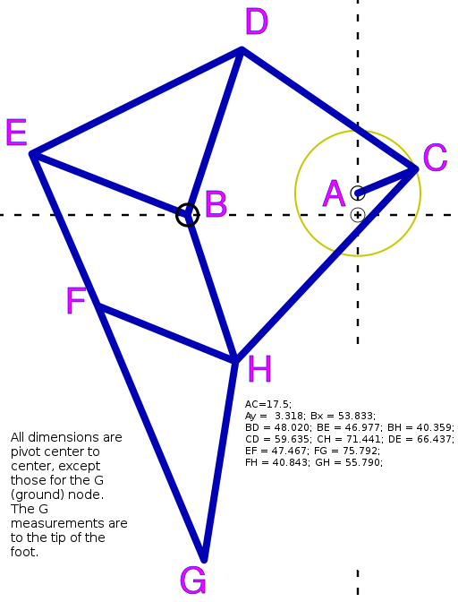
| Snapshots from 3D OpenSCAD drawing and model of steel design for Jansen linkage, Configuration E. |  |
These are annotated renders from the 3D model, with critical dimensions labeled.
Aaron Birenboim| Stack of bearings, on pedal spindle at C |  |
|---|---|
| Hip (BED triangle)
Note: this drawing is dated.
|
 |
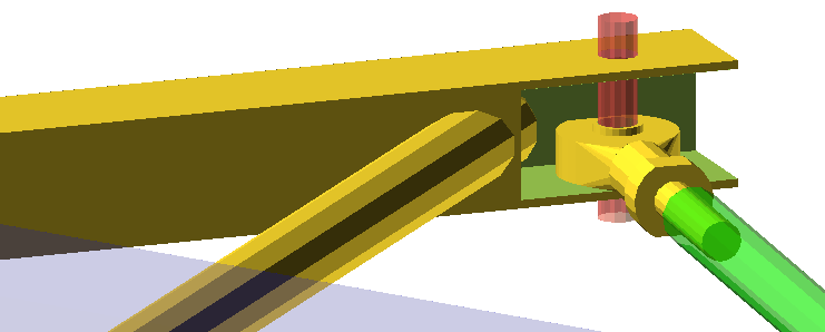
| Cut out one side of 1" square tube for Hip forks.
The push rod for the left side at the D node will have a spacer keeping it toward the inside. On the right side, the spacer will keep the push rod toward the outside. |

|
| Spacers on E node of hip should place the
push rod in the center.
Spacers on the F (knee) node should also center the push rod in the square tube. |

 |
| Profile view of B-joint (axle)
Shows widths collars Note that center of main Hip plane is 1.2cm above bottom of B collar piece. Side of BH fork closer to hip main plane has rod center 0.85cm below top edge of collar, as drawn. Outrigger side of BH fork has rod center 0.85cm above bottom of collar as drawn. NOTE: change the collar widths, then the rod offsets change too. Things need to stay level in Z plane |
 |
| Profile view of H-joint (hamstring)
Make H node on foot piece a thicker guage square (or rectangular) tube, with mounting holes for Heim joints drilled carefully to be parallel on drill press, or preferably mill. Lower foot Heim should be aligned on centerline with the Heim on the F (knee) node. This is the main force plane. Outside is an outrigger. Spacers should place central push rod so that it is parallel with the main plane. Spacing will differ on each side to compensate for the 13ish mm offset of push rods at the pedal spindle. Current drawing is for an M8 bolt. I believe that this is the weakest point of the current design. We may want to try a M10 bolt for the H node. |
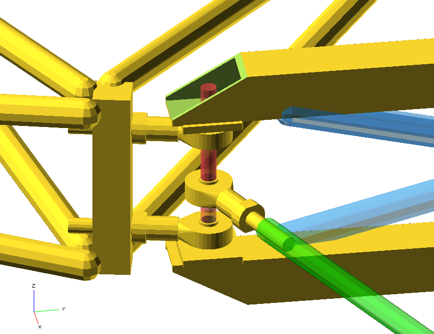 |
| Foot assembly
Note that center of square-tube for shin should also be the center for the inside heim joint at hamstring (H), and center of heim at (F), in the out-of-motion-plane (z) direction. Placement of foot tip, F axis hole, and parallel heim joints at H should be accurately placed using a jig. Connections, round tubes in this drawing, can be altered as desired as long as joint positions are within a very tight tolerance. We may want to rotate the heim pair at H a bit to make it more convenient to weld supports to the square tube seperator. |
 |
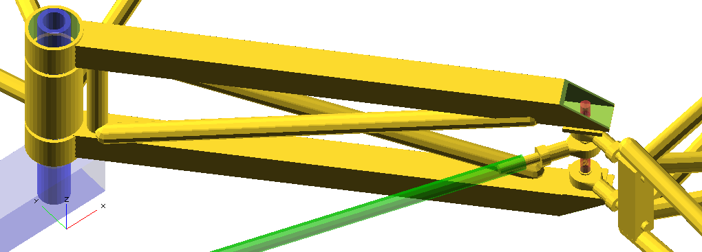
| Hip assembly
Main collar, 7.2cm Centerline for main motion plane is 1.2cm above bottom of collar.
Hence, bottom of 1" square tube should be a mere 0.52mm below the bottom of the collar. For our tolerances, they can be the same. |
 |
| BH brace
I recommend making top and bottom bars with bearing collars for this brace first. Assemble the leg. Tack. Run it through the cycle. Make sure tacks are good. Put cross-braces and spacing on BH after everything is working for extra strength and stiffness as needed. |
 |
| Foot Jig
Pegs on aluminum extrusion frame to align knee pin, foot tube, and hamstring pin. |
 |
| Hip Jig
Pegs on aluminum extrusion frame to align
top bar.
|
 |
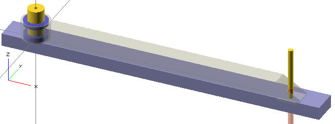
| BH (thigh) Jig
Build each main side of BH independently. Assemble leg, and weld cross braces (if necessary) on assembled leg, to assure proper spacing. This allows us to adjust for small fabrication misalignments before welding this piece to be stiff. Tack, cycle legs. If a tack breaks, align better and tack again. |
 |
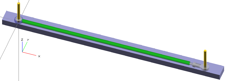
| Crank Link Jig
Two 8mm bolts, screwed into precisely drilled, tapped holes in a bar |
 |
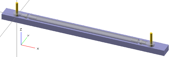
| EF Link Jig
Two 8mm bolts, screwed into precisely drilled, tapped holes in a bar |
 |
| Main bar Jig |
No plans yet.
Try to precise drill 25mm diameter holes centered on square tube centerline. Grind notch at center of tube to align bottom bracket taken from a bicycle frame. Strap frame piece to center bar, with shims as needed. Perhaps flexible mounts that can be squished with screws for fine alignment. Soft Aluminum? Delrin? Gusset notch as needed for extra strength. |
 161017