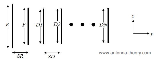
Yagi-Uda antenna design parameters
These were published in 1968 based on experimental results.
I don't totally get them.
Shouldn't R be slightly larger than .5 if the drive element F is .5?
d is the diameter of the elements
Optimal Lengths for Yagi-Uda Elements, for Distinct Boom Lengths
d=0.0085λ
SR=0.2λ |
Boom Length of Yagi-Uda Array, in λ |
|---|
| 0.4 |
0.8 |
1.2 |
2.2 |
3.2 |
4.2 |
| R | 0.482 | 0.482 | 0.482 | 0.482 | 0.482 | 0.475 |
| D1 | 0.442 | 0.428 | 0.428 | 0.432 | 0.428 | 0.424 |
| D2 | | 0.424 | 0.420 | 0.415 | 0.420 | 0.424 |
| D3 | | 0.428 | 0.420 | 0.407 | 0.407 | 0.420 |
| D4 | | | 0.428 | 0.398 | 0.398 | 0.407 |
| D5 | | | | 0.390 | 0.394 | 0.403 |
| D6 | | | | 0.390 | 0.390 | 0.398 |
| D7 | | | | 0.390 | 0.386 | 0.394 |
| D8 | | | | 0.390 | 0.386 | 0.390 |
| D9 | | | | 0.398 | 0.386 | 0.390 |
| D10 | | | | 0.407 | 0.386 | 0.390 |
| D11 | | | | | 0.386 | 0.390 |
| D12 | | | | | 0.386 | 0.390 |
| D13 | | | | | 0.386 | 0.390 |
| D14 | | | | | 0.386 | |
| D15 | | | | | 0.386 | |
| Spacing between directors, (SD/λ) |
0.20 | 0.20 | 0.25 | 0.20 | 0.20 | 0.308 |
| Gain (dB) | 9.25 | 11.35 | 12.35 | 14.40 | 15.55 | 16.35 |
The ACTUAL likely source for the above table might be
the The NBS Yagi Report.
It appears that the reflector is short because they used
a folded dipole (loop) instead of a half-wave dipole. dang.
Still scouring this report for dimensions of the folded dipole (loop)
Folded dipole
Impedance of a typical dipole is around 70 ohms, close to 75 typical for coax feed.
The folded dipole Z ir roughly 4* as high, 280 ohms, which is close to the 300 ohms for typical for twin-lead transmissions lines.
Folded dipoles, center driven, resonate at 0.5λ, 1.5λ,...
driven from the side, they resonate at integer multiples of λ
Rough guide for typical 1/2 wave dipole resonator:
- Reflector 5% longer than driver
- Director 5% shorter than driver
- Reflector spacing between .1 and .25 λ (.2*λ typical)
- Director spacing between .1 and .5 λ, depends on specs and number of directors
Aaron Birenboim
Last modified: Tue Oct 9 05:51:19 MDT 2012