Pages: [1] 2
 ReplyUnsubscribeRSS feedStickyClose   
Author Topic: Dalek
terriko
n00b
Posts: 1
Permalink
Post Dalek
on: July 29, 2012, 21:58
Quote RemoveEdit

We made some quelab dalek buttons tonight and then were talking about justifying them by actually building a dalek, which seems like a potentially fun project.

There are some old BBC instructions floating around:

http://www.aceldama.com/~tomr/media/dalek/blueprints/

(Yup, it really is a plunger...)

And I hear Adric has a wheelchair base we might be able to build on, or I was quite amused by the idea of making a dalek roomba...

Thoughts? Links?

adric
Administrator
Posts: 178
Permalink
Post Re: Dalek
on: July 30, 2012, 10:01
Quote RemoveEdit

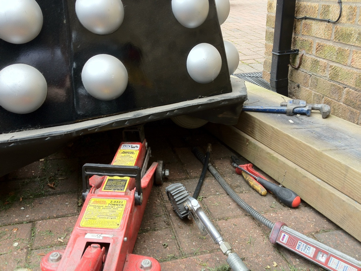
Well i have this. Image The wheeled craft... not the industrial gnome! (He moved off to california)

its beefy! well built solid steel construction, 2 pneumatic tires 2x 24v15A right angle permanent magnet motors. It was the base of a very large electric wheelchair.

A whisk and a plunger should not be hard to find! :P

The above wheeled craft is available free of charge for members to build on, (its in my garage now, because to bring it to the lab we first need a few members to help out on the sorting and clearing of stuff so we have the space to store it and work on it. )

-Quelab, Come make something!

Mr.What
Administrator
Posts: 197
Permalink
Post Re: Dalek
on: August 7, 2012, 10:12
Quote RemoveEdit

Is that two reversible DC motors? So we need two large H-bridges (24v, 15A) I propose an Arduino controller, with Bluetooth serial (like I used on my smoker). Then an Android app to drive it. Any Android developers listening?

adric
Administrator
Posts: 178
Permalink
Post Re: Dalek
on: August 7, 2012, 13:54
Quote RemoveEdit

Yes, 2 wires coming from each motor, if you reverse current it reverses the motor. we could probably get buy with lower rated stuff, the motors work with quite a bit of torque at 12v, using 10AH batteries, unless we need a Dalek that can smash through walls (like the Kookaid Man)

-Quelab, Come make something!

Walter
Administrator
Posts: 30
Permalink
Post Re: Dalek
on: August 9, 2012, 11:59
Quote RemoveEdit

Materials needed, from the BBC instructions:

    28 lbs modelling clay
    paper/polystyrene
    1 roll 500 mm bandage
    28 lbs fast-setting potter's plaster
    4 sq yds hessian scrim
    .5 pint shellac
    1 tin car wax
    .5 pint PBA release agent
    2 oz accelerator
    2 oz catalyst
    strips of glass matt
    2lbs gelcoat resin
    6lbs layup resin
    acetone
    soap and water
    1 tub barrier cream
    sink plunger
    2 car parking lights (for flashing lights on head)
    2 6V .3amp bulbs and holders
    6 volt battery

    1.5mm ply 1 sheet 5'x5'
    6mm ply 4 sheets 5'x5'
    9mm ply 1 sheet 8'x4'
    15mm ply 1 sheet 10'x4'
    12mm wooden dowel
    27mm wooden dowel
    2 wooden balls 95mm diameter

    24 polystyrene balls 100mm diameter
    6 ball bearings 6mm
    30 gauge fine aluminum mesh 275mm x 1470mm
    24 gauge large aluminum mesh (2 strips) aluminmum 655mm x 180mm
    1425mm x 150mm
    and two strips sof aluminum 651mm x 10mm
    40mm x 170mm

    36mm aluminum or plastic tube 455mm
    40mm aluminum or plastic tube 615mm
    3mm steel rod 315mm
    15mm rod 270mm
    brass shim strip
    aluminum angle
    ribbed rubber flooring foam strip
    3 plastic rotating castors 1.5in to 2in in diameter
    perspex 2mm 80mm x 80mm
    2 brass rings (internal diameter 28mm, cut to 10mm long)
    screws, nuts, bolts, snap rivets, fast-drying enamel paint

adric
Administrator
Posts: 178
Permalink
Post Re: Dalek
on: August 9, 2012, 13:09
Quote RemoveEdit

Well the bbc's build list looks a dated/expensive, I suspect with an artistic eye and a little work we could probably fab something better cheaper.

and WTF is "1 tub barrier cream"

Im thinking we might really need to build something ive been interested in building for a while which is a smallish vaccumformer. rather than buying and cutting 24 polystyrene balls to make the dalek bumps we buy 2 and vaccuform strips of 4 bumps.

-Quelab, Come make something!

Walter
Administrator
Posts: 30
Permalink
Post Re: Dalek
on: August 9, 2012, 14:14
Quote RemoveEdit

Expensive? But it says the approximate cost is £15!

What's a vaccumformer?

Geoff
Administrator
Posts: 21
Permalink
Post Re: Dalek
on: August 17, 2012, 16:50
Quote RemoveEdit

Oo, vacuformers are cool! It's basically a way to make plastic parts from a positive mold, using heat (to make the plastic pliable) and vaccum (to suck the plastic sheet onto the mold).

http://makezine.com/go/vacuform

adric
Administrator
Posts: 178
Permalink
Post Re: Dalek
on: August 23, 2012, 11:00
Quote RemoveEdit

Image (photo found online, both cute, and may have useful construction/clues.

-Quelab, Come make something!

adric
Administrator
Posts: 178
Permalink
Post Re: Dalek
on: August 24, 2012, 17:13
Quote RemoveEdit

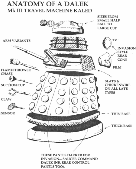
Another bit of info.
Image

-Quelab, Come make something!

adric
Administrator
Posts: 178
Permalink
Post Re: Dalek
on: August 24, 2012, 17:20
Quote RemoveEdit

Quote from Walter on August 9, 2012, 14:14
Expensive? But it says the approximate cost is £15!

What's a vaccumformer?

Expensive! that parts list looks closer to $200+

As for a vacuformer, they use them on mythbusters all the time, (also just about any blister packages containing any gadget you have ever had was vacuformed.) its a cheap way to make a mold or pull a shape into hot plastic.

you put an object down on something like a small airhockey table, (but instead of blowing out air, you suck it) then you place a sheet of heated plastic over the top and it gets sucked down tight. then it cools.

-Quelab, Come make something!

adric
Administrator
Posts: 178
Permalink
Post Re: Dalek
on: August 24, 2012, 18:23
Quote RemoveEdit

And an Awesome papercraft dalek! must setup a printer soon and make!! http://audrey-2.deviantart.com/gallery/#/d5ccg2k

-Quelab, Come make something!

Mr.What
Administrator
Posts: 197
Permalink
Post Re: Dalek
on: September 10, 2012, 10:45
Quote RemoveEdit

Ordered power MOSFET's. When do we start?
Would it be a mess to bring it to Maker Faire, and play with it there?

Plan: Arduino + Serial-over-Bluetooth module. Dual H-bridges. ASCII serial command (at least for testing) so we can drive it from a bluetooth terminal emulator.

Should I use 4 DIOs for each H-bridge and do all the direction switching in software, or should we add some logic to do a "direction" pin and a speed pin (2 DIO's per H-Bridge).?

Mr.What
Administrator
Posts: 197
Permalink
Post High-power H-Bridge
on: September 12, 2012, 20:38
Quote RemoveEdit

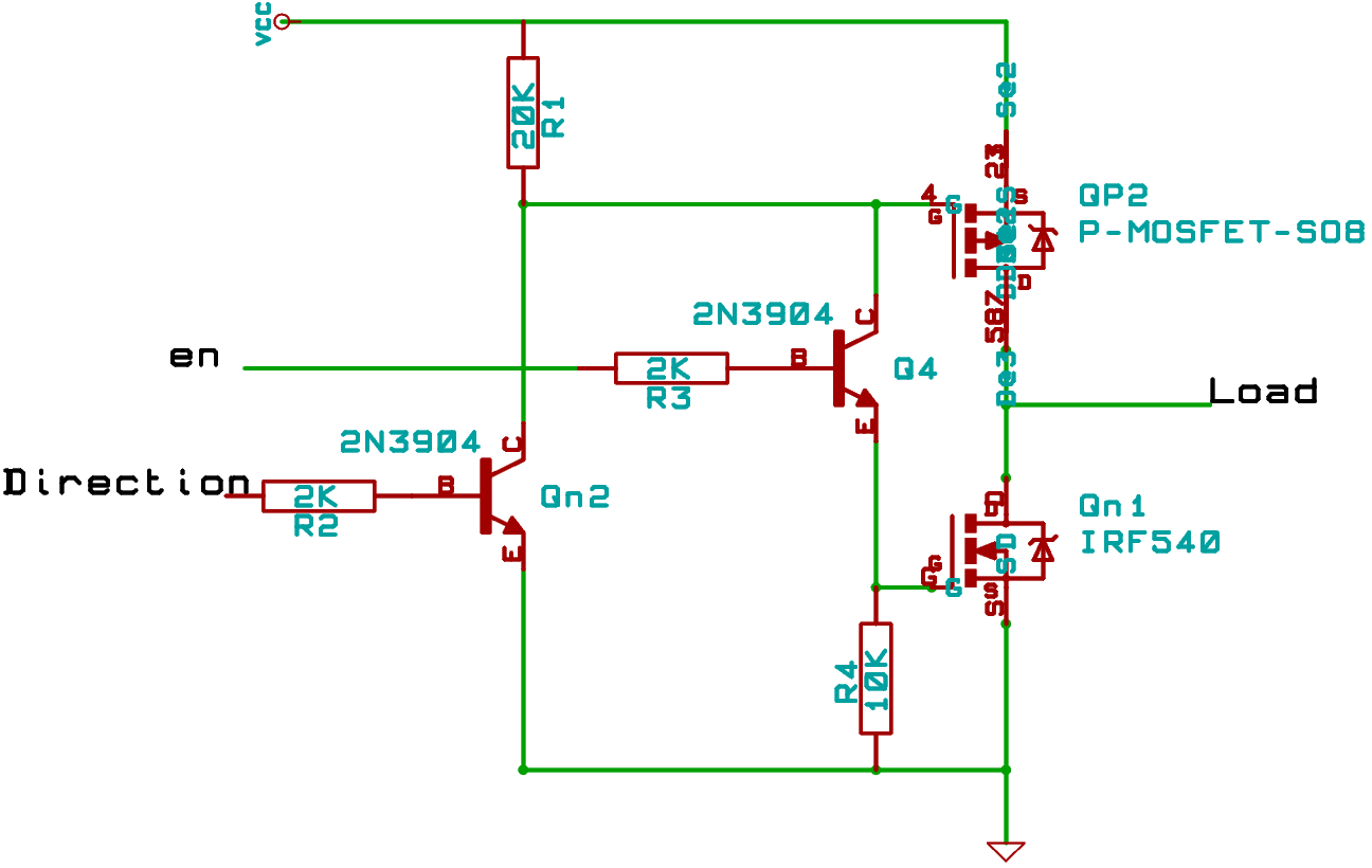
After letting the smoke out of my little 3-phase controller, I'm rethinking how to make a safe half-bridge. Here is my latest idea. We have a direction indicator, which is either 0 or 5v. We will put an inverter on this line to feed to the other side of the full bridge.

The speed will be set by the "en" (enable) line, which will be PWM. When the half bridge is low-enabled, the en line will PWM the ground side of the motor. When the high side is enabled, it is always on. Note that the en pin does nothing unless the half bridge direction line is grounded.

sorry for the messy schematic. this is my first eeschema drawing, still have much to learn.
Image

... on farther review, the above has an error. R1 will need to be more like 2K, and R4 like 100K. And it is a bit touchy with working over a wide range of voltage.

After rethinking the problem more, I think I'll go with an optoisolator based design. AND dir and !dir signal with en signal. 2 Wires off of the TTL board to H-bridge. Run opposing LED's from optocoupler across these two wires, and we are guaranteed only 1 can light.... or... have one DIO be PWM (en) and another for direction. When going in reverse, note that PWM level is inverted... that is better. avoid inverters and and gates!

With the optoisolators, I can have isolated high power on a separate board, and only need 2 wires per H-Bridge to control it.

Mr.What
Administrator
Posts: 197
Permalink
Post isolated H-bridge design
on: September 13, 2012, 07:48
Quote RemoveEdit

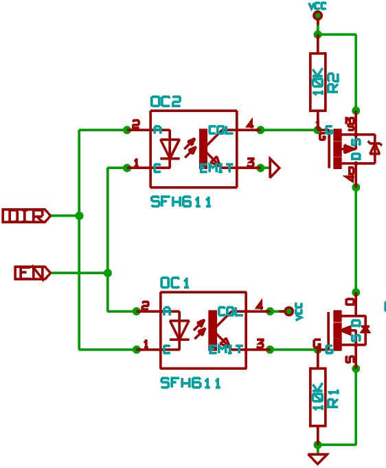
Here's the schematic for 1/2 of the isolated H-Bridge design. DIR is a straight DIO, while EN is PWM. Software will need to note that when going forward, EN is active-high, when in reverse, EN is active low. So when going backwards, command analogWrite(255-speed).

This only needs 2 wires coming from the uController board.
Suggest putting 120 ohm resistors in series with DIR/EN lines both for safety, leaving the low-power board, and as current limiters to optocoupler LED's.

For other side of H-bridge, just flip the DIR and EN leads.

Image

They recommend 470ohm for TTL, but since each of our diodes goes through 2 resistors (one on each side), and each line drives 2 parallel diodes, divide by 4, which is roughly 120 ohm.

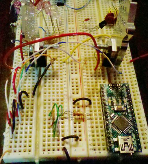
Here is the test circuit for Arduino. Still waiting for opto-coupler chip to arrive.
Image
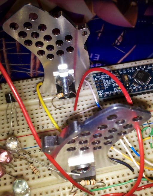
Heat sinks are connected to PN-pair drains, and will also serve as motor connection contacts.
Image

adric
Administrator
Posts: 178
Permalink
Post Re: Dalek
on: September 14, 2012, 13:11
Quote RemoveEdit

cool! your already further along the plan than we were when i got the thing. we were working on a 555 timer based pwm. :}

-Quelab, Come make something!

Mr.What
Administrator
Posts: 197
Permalink
Post opto-isolated H-bridge physical layout
on: September 17, 2012, 14:44
Quote RemoveEdit

Got an opto-isolated H-Bridge motor controller running. Here's a drawing of the physical circuit layout. P-MOSFET's are pinkish, N are blueish, ground bus is blueish, high-side bus is pinkish, heat-sinks are blue-gray, and optocoupler chip is green
Image

Mr.What
Administrator
Posts: 197
Permalink
Post Inner Tubes
on: September 19, 2012, 07:50
Quote RemoveEdit

Ordered 2 inner tubes for the rear wheels.

I think electronics are OK. I had a version of the firmware with a bug. Will update, and I think all will be OK. Seems to drive motors fine.

Need to mount arduino and motor drivers safely. Plan to use an acrylic tile. Still need to mount manual drive pots on acrylic plate. All parts are sitting inside the base now.

I need some #10 nuts, bolts, washers to attach the battery to the drive circuits. I have some #6 screws and nuts to attach the motor cables to the driver circuits, but I forgot them at home last night.

There are some of those automotive blade connectors in the "connectors" drawer to the right of the electronics bench. I was using screw connectors, but have been making little connectors/converters from the blade connectors on the bench.

Still looking for a volunteer to write an Android app to send speed commands via serial-over-bluetooth. I plan on the following (initial) command set:

   Lnnn    : left  motor, speed -255 to 255
   Rnnn    : right motor, speed -255 to 255

0==stop. negative values are reverse speed.

Do fancy scaling/mapping of controller position to speed commands on the phone/tablet.

adric
Administrator
Posts: 178
Permalink
Post Re: Dalek
on: September 19, 2012, 12:41
Quote RemoveEdit

with the values coming from BT-Serial, what happens if the dalek goes out of bluetooth range? does it continue or will it require constant updates from the controller/deadswitch?

-Quelab, Come make something!

Mr.What
Administrator
Posts: 197
Permalink
Post Re: Dalek
on: September 20, 2012, 15:16
Quote RemoveEdit

Deadman watchdog. No command for X milliseconds == full stop.
I will expand X to 2000 or 3000 for testing. In operation, I will set X to something more like 250. Control app should be sending a constant stream of speed command updates/repeats.

Mr.What
Administrator
Posts: 197
Permalink
Post Updated schematic for full isolated H-Bridge
on: September 25, 2012, 08:51
Quote RemoveEdit

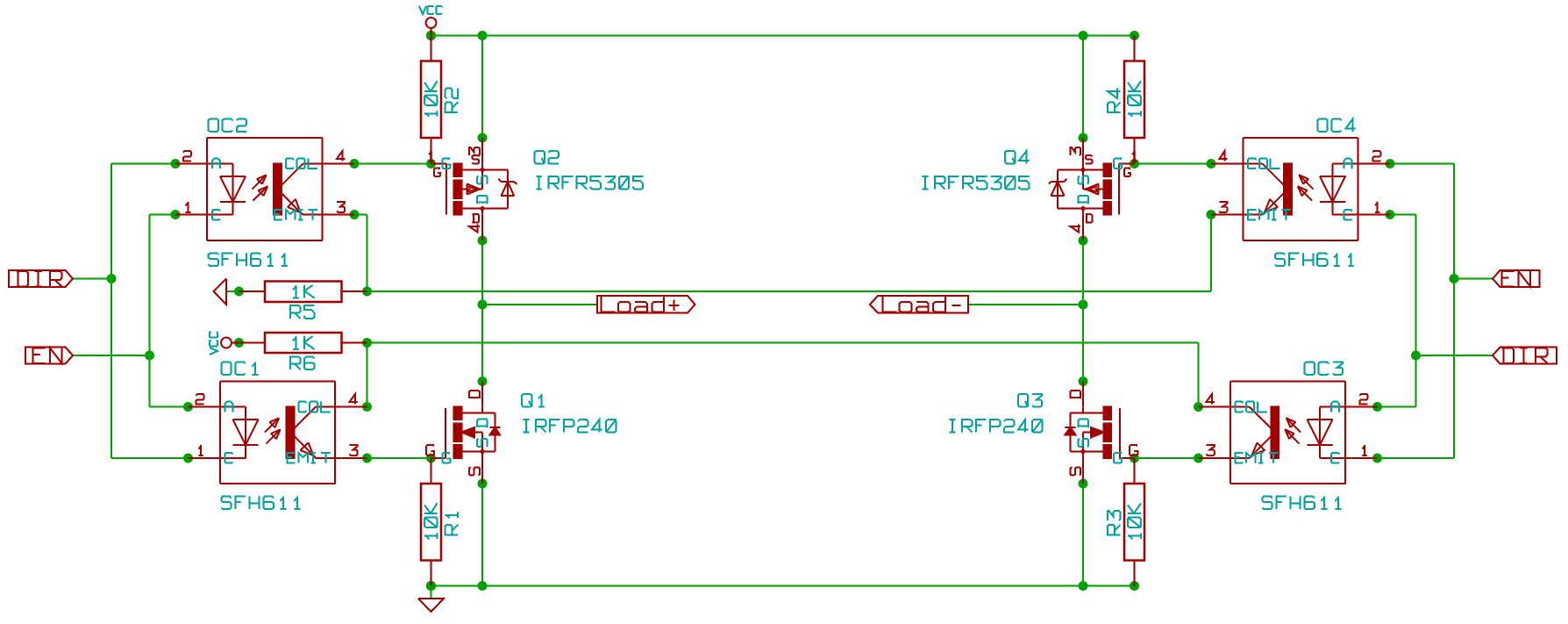
Updated schematic, as implemented, for the full H-Bridge optoisolated controller, which can be driven by PWM signals:
Image

Mr.What
Administrator
Posts: 197
Permalink
Post Manual override drive panel installed
on: September 27, 2012, 06:09
Quote RemoveEdit

Manual motor control panel installed. Slider pots for tank-style motor control, with deadman-enable switch in the middle.

Next: Get some sort of seat assembly installed so we can ride it, and perhaps mount the electronics to that assembly in a manner so they are protected.

Mr.What
Administrator
Posts: 197
Permalink
Post source code for motor drive
on: September 27, 2012, 11:19
Quote RemoveEdit

for completeness, here is the source code for the motor driver.
There is one main method,

    MotorDrive::setSpeed(int x)

where x is a number from -255 to 255. Negative values are for reverse.

Code is typical minimalist uController stuff.
You need to directly set up exposed state variables in your initialization sequence, like...

#define MOTOR_DECEL_FACTOR 4
MotorDrive MotR;
...
MotR.Pin.REV = 4;  // DIO pin for REV signal
MotR.Pin.EN  = 5;  // PWM enabled DIO pin for EN signal
MotR.setSpeed(0);  // make sure we are stopped at init

Main class:

class MotorDrive 
{
public:
  struct {
    int REV;  // reverse direction indicator, 1==Reverse
    int EN;   // Enable/speed pin. 255 is fast forward, but stopped reverse
  } Pin;
  int speed;  // current speed
  // Set speed -255 for max reverse, 255 for max forward
  void setSpeed(const int spdReq)
  {
    int spd = spdReq;
    if (spd < -255) spd = -255;
    if (spd >  255) spd =  255;

    if ((long)spd * (long)speed > 0)
      { // no change in direction.  just change EN value
        if (spd > 0)
          {
            if (spd ==  255) digitalWrite(Pin.EN,HIGH);
            else              analogWrite(Pin.EN,spd);
          }
        else
          {
            if (spd == -255) digitalWrite(Pin.EN,LOW);
            else              analogWrite(Pin.EN,255+spd);
          }
        speed = spd;
       //Serial.print(F("\t\tsame direction\t"));Serial.println(speed);
        return;
      }

    // check current REV pin state
    int revState = digitalRead(Pin.REV);

    // Weather we are stopped, or have a change in direction,
    // shut motor down first.
    if (revState)  digitalWrite(Pin.EN,HIGH); // HIGH to stop, rev mode
    else           digitalWrite(Pin.EN, LOW); //  LOW to stop, forward mode

    int prevVel = (speed > 0) ? speed : -speed;
    if (prevVel>10)
      { // kind of fast.
        // wait a while to slow down before allowing more commands
        Serial.print(F("\t\tDirection change... wait a bit"));
        delay(prevVel*MOTOR_DECEL_FACTOR);
      }

    if (spd != 0)
      { // should do these simultaneous, but I think it
        // is safe to allow sub-microseconds of reverse direction drive
        if (spd < 0)
          {
            analogWrite(Pin.EN,spd+255);
            digitalWrite(Pin.REV,HIGH);
          }
        else
          {
            analogWrite(Pin.EN,spd);
            digitalWrite(Pin.REV,LOW);
          }
      }
    speed = spd;
    Serial.println(speed);
    return;
  }
};
Mr.What
Administrator
Posts: 197
Permalink
Post Following a beacon
on: October 4, 2012, 05:07
Quote RemoveEdit

Any ideas for simple ways to have the robot follow a beacon?

I have found cheap (<$2) IR sensor/demodulators. They will ground a pin when they detect an X KHz modulated IR signal. (X can have several values int the 30 to 50 KHz range). Three of these on a servo should be able to detect a beacon direction.

I think we can make a beacon with some IR LED's (matched wavelength), and a simple RC oscillator. I think Ray knows how to build a really simple one with nothing but an inverter, resistor, capacitor. Simpler than a 555.

I saw one interesting project which cannibalized 3 ping sensors (sonar) for this. One transmitter, with wireless trigger, then two sensors (TX disabled). Each sensor could give distance to ping source. But it seems like coordinating the ping TX from the beacon might be a pain.

Another idea is an IR tracking camera. A Wii controller has one.
They speak Bluetooth. I don't know how hard it would be to have a bluetooth module getting IR spot locations from a Wii remote.

Better ideas?

Mr.What
Administrator
Posts: 197
Permalink
Post Directional Antenna
on: October 7, 2012, 08:32
Quote RemoveEdit

I think that a loop antenna will be the easiest for me to use as a directional antenna. A full wave resonant loop will have a diameter of 22 cm. A simple single loop should do the trick, and have an impedance of about 100 ohms.

/wordpress/wp-content/uploads/2012/10/0071475745_chap05.pdf

http://quelab.net/wordpress/wp-content/uploads/2012/10/0071475745_chap05.pdf

Mr.What
Administrator
Posts: 197
Permalink
Post IR beacon
on: October 8, 2012, 05:17
Quote RemoveEdit

Geoff mentioned an IR beacon/detector pair. They come in tranceiver pairs, $50/pair, $27 ea. Only claim 15' range, only indoors in benevolent conditions. http://www.pololu.com/catalog/product/701.
They may share a code in their transition, so they won't interfere with other IR communication in the room.
They use 4 fixed detectors, and triangulate.

I'm still open to this, but am still looking into an RF solution.

I also wonder if an ultrasonic beacon will work. I don't know much about them, but Electronic Goldmine sens ultrasonic transmitters and receivers for about $2 each. I'm not sure what support circuitry/logic they may need.

Mr.What
Administrator
Posts: 197
Permalink
Post scaffolding
on: October 8, 2012, 05:21
Quote RemoveEdit

I think we'll do a (mostly) bolted scaffolding to attach the shell, and electronics too. We talked about all bolted, but I think that the main T at the back, hanging over the drive wheels is a bit stressing for bolts. I'll just do one weld for that main, back T structure, with a 2" angle iron for the main post, attached with the U bolts as the seat was, and 1.5" angle iron for the main bar. The rest of the structure will be from hardened steel bedframe.

Mr.What
Administrator
Posts: 197
Permalink
Post Yagi-Uda design
on: October 8, 2012, 07:52
Quote RemoveEdit

Found one table on Yagi-Uda design. Seems odd (or dated) in that the reflector seems to be shorter than the driven element.
http://boim.com/misc/yagiTable.html

Mr.What
Administrator
Posts: 197
Permalink
Post Radio RX
on: October 11, 2012, 05:25
Quote RemoveEdit

/wordpress/wp-content/uploads/2012/10/rcr433rp_Mouser433MHz_4800baudRX.pdf

Datasheet for the RX modules I got on end-of-life closeout at Mouser.
50 Ohm antenna pin, "analog" out pin, and digital out pin.

I'm not sure of the analog output has some sort of automatic gain control. I hope not.
I would like to be able to use the analog output pin (through an LPF?) as a signal strength indicator, so I can use this radio RX for transmitter hunting.

This module has VERY small surface mount parts.
It may be difficult to attach to an internal node for a signal strength indicator.

I have some 433MHz TX's on order from another supplier.
I would like to set up a TX that does some sort of PWM signal that we can try to track from the robot.
Perhaps 66% PWM duty-cycle for "1", 33% PWM duty-cycle for "0".
Put the RX antenna on a servo, so it tracks the direction of the TX.
If the received bit is "1" try to move towards the TX. if it is "0" just track it's direction, but do not attempt to move towards it.

That way, a person holding the TX can hit a button, and the robot will try to get to them. Release the button, and the robot stops.

http://quelab.net/wordpress/wp-content/uploads/2012/10/rcr433rp_Mouser433MHz_4800baudRX.pdf

Add a ping sensor to keep the robot from running into things, and we may not need RC commands to drive the robot.
Just let it follow the beacon.

If we do a loop antenna, with peak sensitivity in 2 directions, you could get behind the robot with the TX, and "push" the robot around too.

Quick Reply:

Pages: [1] 2
 ReplyUnsubscribeRSS feedStickyClose   
Mingle Forum by cartpauj
Version: 1.0.34 ; Page loaded in: 0.094 seconds.

[Edit Page]
 

Comments are closed.

Hacknight Edit
Jun 18 @ 7:00 pm – 10:00 pm
Our twice-weekly open house. Come learn what we’re all about! This is when both members and non members are encouraged to come in and work/start/help [...]