$URL: svn+ssh://mrwhat@ssh.boim.com/home/mrwhat/svn/Walker/trunk/BuildingLC.html $
$Id: BuildingLC.html 427 2014-08-23 20:42:39Z mrwhat $
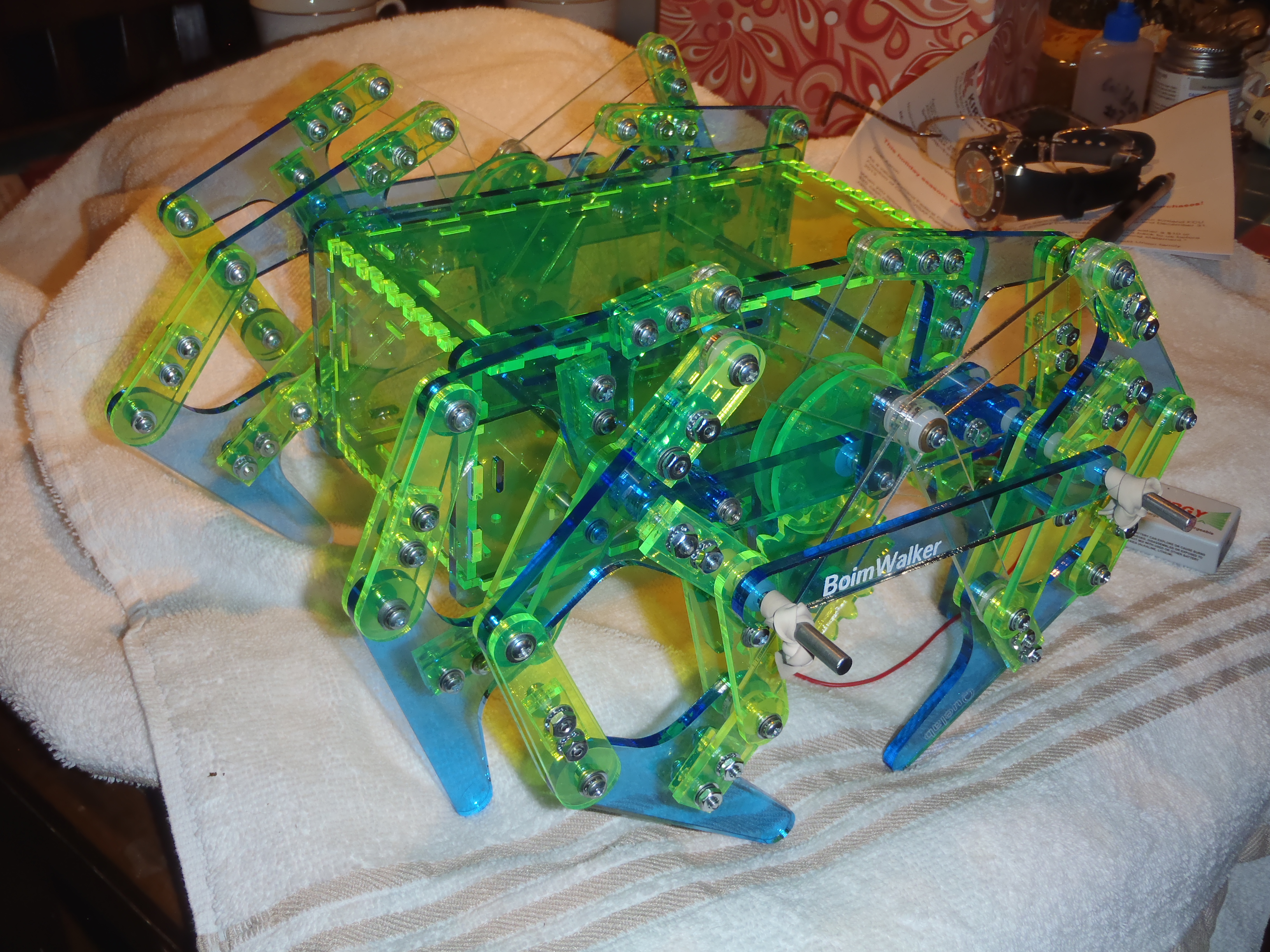
Building laser cut Sleipnir Walin8r
I am currently re-working the drawings for the new configuration, E,
and breaking up the drawings into smaller groups.
This is more convenient for Quelab's new laser cutter,
and the drawing groups can be easily manipulated in Inkscape for
crating larger drawings for services like Ponoko.
These drawings will help explain my conventions for naming parts
of the linkage:
- General note on glues for Acrylic:
- Do NOT use CA cement on or near acrylic. The fumes will mar and glaze the surface.
Welding agents work wonderfully when bonding acrylic to acrylic.
I am told that acetone will work, but it is slow, and may not make as strong a weld
as the Weld-On chemicals.
The weld strength is not likely to be an issue for this assembly, which does not
experience any severe stresses.
I have been using Weld-On #3 which is very fast.
I am told that Weld-On #4 will be a bit slower and make a stronger weld.
I am finding #3 too fast, and rather hard to work with,
so I will recommend getting #4 if you can.
Welding is unnecessary for most of this project, simply an asthetic decision.
However, welding the main drive gear to it's guidance plates should make the
gear teeth a little stronger, which might be a good idea.
It may not be necessary to epoxy the motor gear to the shaft, but it should
certainly make that connection stronger, and perhaps longer-lived.
For a complete chassis hardware setup, using 3/16" OD standoff hinges you will want :
- (2) gearhead motors
- motor driver module
- (2) 3/16" OD steel rods, 1 foot long
- Acrylic welding cement, such as Acetone, Weld-on #4 or Weld-On #3.
- Epoxy capable of boinding acrylic to metal, such as JB-Weld.
- (24) 1/2" long, 3/16" OD standoffs for #4-40 screws
- (32) 3/16" long, 3/16" OD standoffs for #4-40 screws
- (2) #4-40 0.25 to 0.75 inch threaded rods.
Can be made by cutting the head off of a screw, and then cleaning the threads.
- (76) 1/4" long #4-40 pan or round-head screws
- (182+) #4 flat washers
- (8) #4 larger diameter flat washers, if available. (standard diameter is OK)
- (98) #4 internal tooth lockwashers
- (98) #4 internal tooth lockwashers
- (50) #4 external tooth lockwashers
You will need less screws, nuts, washers if you weld some of the fork stackers.
The 3/16" OD standoffs are fairly rare.
I can sell some for slightly above cost.
I intend to offer full hardware packages, including these standoffs, soon.
Chassis assembly
Chassis assembly is into several major stages.
The first stage involves the use of epoxy which may take a significant amount
of time to set.
This stage can be performed in parallel with the next two stages while
waiting for adhesives to cure.
- Drive and main bar assembly
- Leg sub-assemblies
- Payload assembly
- Main chassis integration
This completes the base of a fairly typical robot chassis, with dual motor control.
I will be publishing my design for running this chassis over a Bluetooth remote
control soon.
It uses an open-source Android app to send control commands to a Bluetooth receiver,
attached to an Arduino nano compatible microcontroller module.
The motors are controlled from a fairly common LM298 based motor control module.


 Last modified: 131007