 Screw threaded rod into one 1/2" standoff such that when the main drive gear
is in place it is centered on the threaded rod.
Screw threaded rod into one 1/2" standoff such that when the main drive gear
is in place it is centered on the threaded rod.
 Place a small amount of epoxy (JB-Weld) onto the threaded rod near the standoff, and put the drive gear into place.
Screw other 1/2" standoff onto the threaded rod to form an axle, gently, snug, just slightly finger tight. Do NOT over tighten. The epoxy will create the solid axle. Excessive torque will only crack the acrylic.
If any epoxy got onto the exposed parts of the standoffs, clean it off.
 Using spacers and washers or clothes pins, hold side pannels loosely in place on either side of main drive gear.
Inject some welding solvent between the gear and side pannels, and gently snug the side pannels into intimate contact with a screw.

Set these parts aside until the adhesives have fully cured.
 Use the 7/8" screws, 4 flat washers, 4 locking washers,
and 2 nuts to mount the motor mount tab
to the main arm using two of the wider stackers.
Remember to use the internal tooth locking washers between screw heads and flat washers,
and use the external tooth locking washers between nuts and flat washers.
Use the 7/8" screws, 4 flat washers, 4 locking washers,
and 2 nuts to mount the motor mount tab
to the main arm using two of the wider stackers.
Remember to use the internal tooth locking washers between screw heads and flat washers,
and use the external tooth locking washers between nuts and flat washers.
| Need photo of current motor mount design, with motor tab fork spacers being mounted below the motor. |
 Score one side of a (large diameter) washer, both sides of an acrylic hub,
and a small area near the center of the motor gear on both sides.
Score one side of a (large diameter) washer, both sides of an acrylic hub,
and a small area near the center of the motor gear on both sides.
Place the (large diameter) washer over the axle.
Put a small amount of epoxy (JB-Weld) at the junction of the axle and the washer.
Install the drive gear over the washer,
which should compress and smear the epoxy over the surface of the washer.
Place another small dab of epoxy on the drive gear, around the motor axle.
Install the small hub piece over the motor gear, which should compress and smear the epoxy over the surface of the hub.
Place another small puddle of epoxy over the hub and motor axle tip.
Attach motor and attach it to a small voltage source.
While the motor spins, check that the motor gear does not wobble as it turns.
Tilt the gear as necessary such that it wobbles as little as possible.
Once you have aligned the motor gear with the motor spin axis
to the best of your abilityare, double check that the epoxy is in content
with all parts of the motor gear assembly, and that no epoxy is on
the motor, or on the motor shaft near the motor.
Carefully place the motor over the edge of a table and hold in place
to cure.
One easy way to do this is to tape the motor to the edge of a table
with the gear out of contact with any object other than the motor axle.
Spin the motor to double check that the gear is still well-aligned.
Tilt if necessary for the best possible alignment.
Allow the epoxy to cure.
| Photo shows glued gear. Do not pay too much attention to how it is mounted. Photo was from original suggestion to clamp the gear straight. Experimentation has shown that it is more effective to run the motor, gently align the gear by hand, and leave to cure un-clamped. |

|
Repeat for the other motor/gear assembly.
Originally, it was suggested to cement the plastic hub to the motor gear. I am no longer recommending that, since it may make it harder to mount the gear to the drive shaft with proper alignment. It was found that an epoxy bond provided more flexibility for proper gear alignment.
 Place 1 1/8" screws through one side of the main bar with
a washer to protect the acrylic, and a lock washer under the head of the screw.
Place 1 1/8" screws through one side of the main bar with
a washer to protect the acrylic, and a lock washer under the head of the screw.
 Place three main-bar axle spacers on each screw.
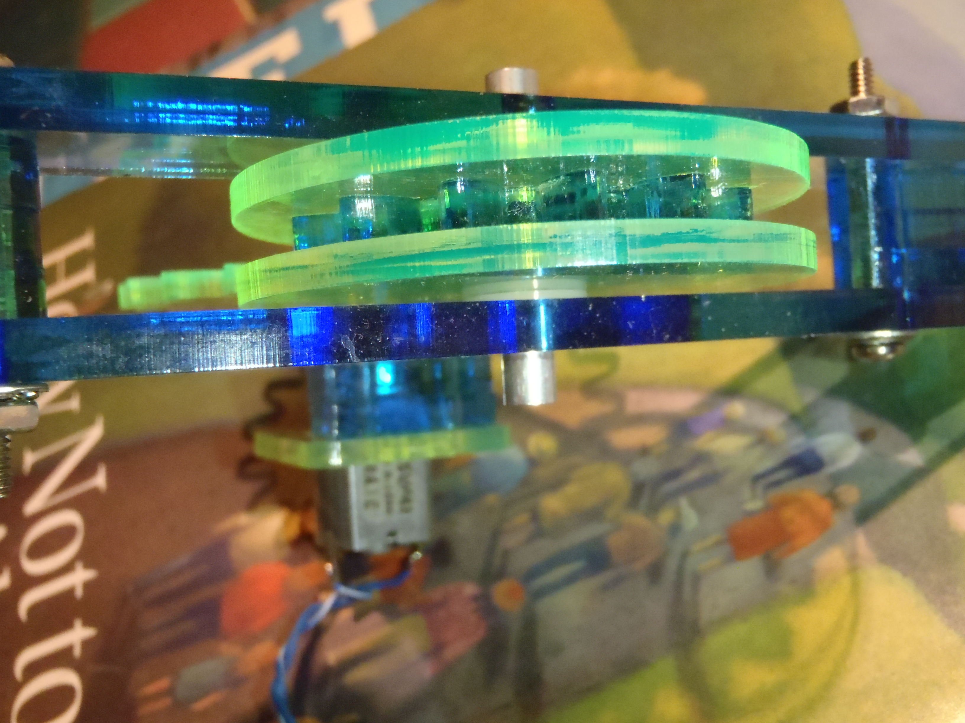 Place a nylon washer on either side of the main axle/gear assembly.
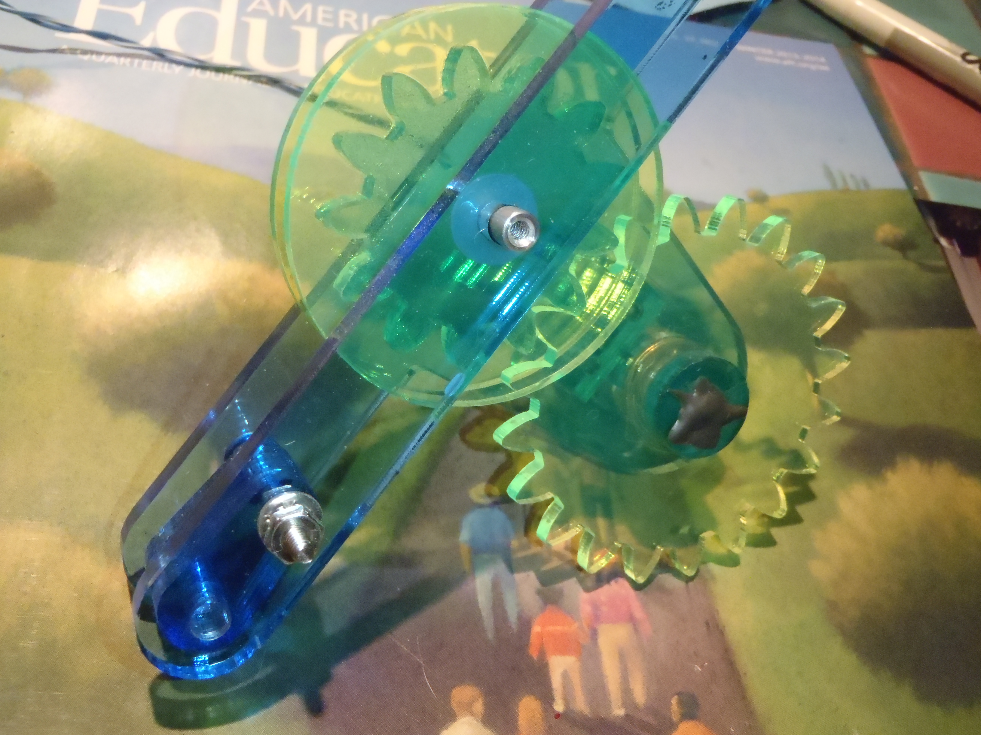
Install the motor/gear assembly on to the main bar, with the main drive gear in place over the motor gear.
Fit all parts into the main arm. Make sure that the placement of the motor gear places the gear near the middle of the drive gear/axle assembly.
Install the other side of the main bar, over the other side of the gear axle.
Secure with a washer, lock washer, and nut over the two 1 1/8" screws.
Finger tighten these nuts, then align the spacers with the axle holes.
Tighten the 1 1/8" screw with the axle in place.
Use the axle to align the spacers on the other side similarly, and tighten the screw on the other side.
Remember to NOT over-torque these screws. The plastic can split. Just bit more than finger-tight with screwdriver should be sufficient.
Repeat this procedure to build the other main-arm, motor-drive assembly.
Attach a battery (9v or your pack) to each motor, and check that the motors drive the main axles smoothly.
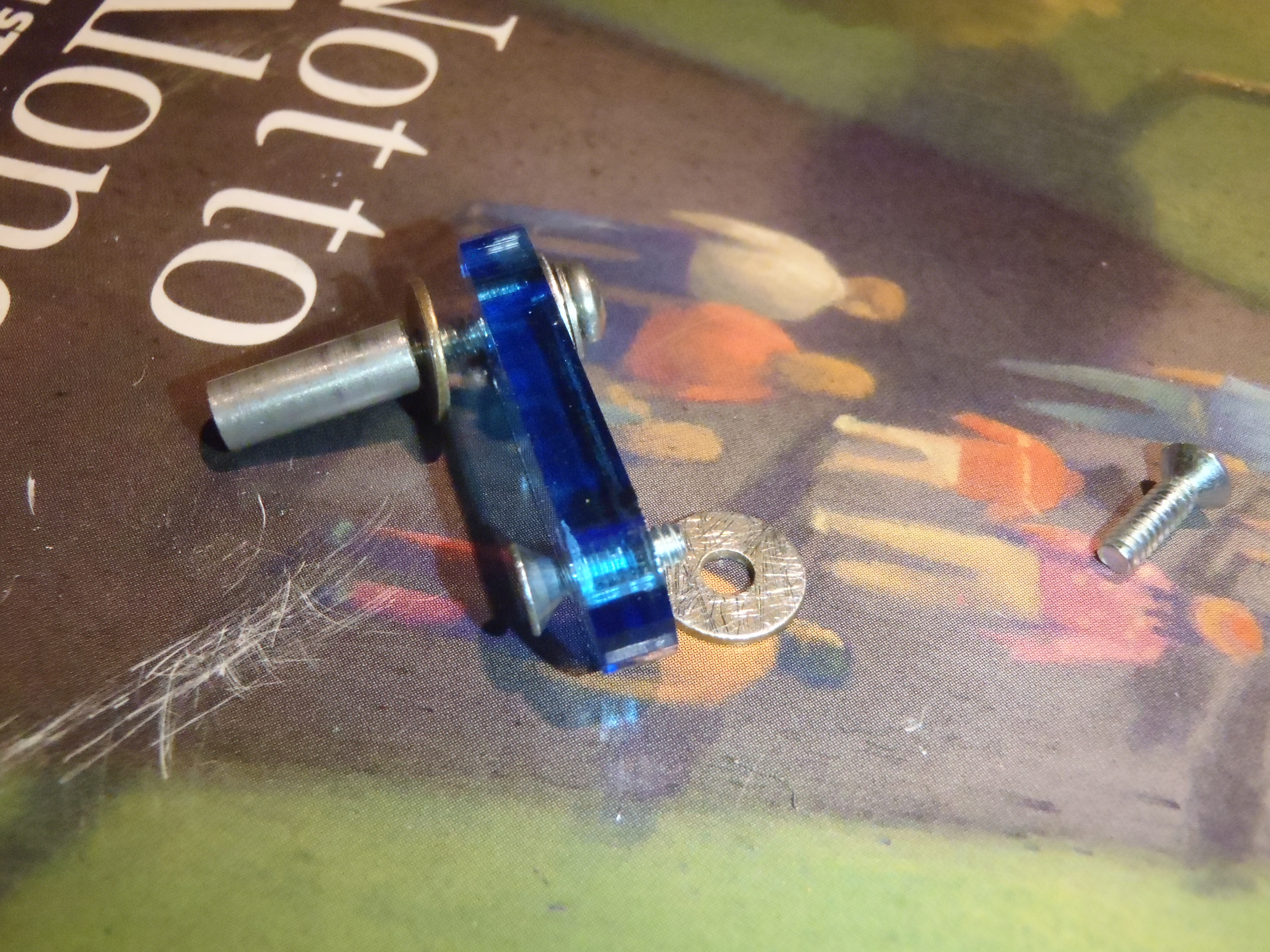
 Put an internal tooth lock washer and a washer on a 1/2" screw, in that order.
Thread the screw through a crankarm, starting on the side opposite of
the counter-sunk hole, on the edge opposite of the counter sunk hole.
Plase a wide flat washer over the screw then thread a 1/2" standoff onto the screw.
Tighten the screw into the standoff.
As always, do not over-torque, it will only split the acrylic.
However, do tighten the screw enough to engage the lock washer, since this screw
will be hard to access after the crank arm is glued to the main drive gear axis.
Put an internal tooth lock washer and a washer on a 1/2" screw, in that order.
Thread the screw through a crankarm, starting on the side opposite of
the counter-sunk hole, on the edge opposite of the counter sunk hole.
Plase a wide flat washer over the screw then thread a 1/2" standoff onto the screw.
Tighten the screw into the standoff.
As always, do not over-torque, it will only split the acrylic.
However, do tighten the screw enough to engage the lock washer, since this screw
will be hard to access after the crank arm is glued to the main drive gear axis.
Attach the spindle standoff in the same manner to the other 3 crankarms.
 Roughen the countersunk hole in the crank arm with a file or small piece of sandpaper.
 Also roughen the underside of the flat-head screws (the ones with the conical heads, flat on top where the screwdriver goes).
You may also want to roughen the side of the crankarm opposite of the counter-sunk hole near the screw hole, the flat washer, and the top of the 1/2" standoff to make the
surfaces clean and rough to stick to the epoxy better.
Also roughen the underside of the flat-head screws (the ones with the conical heads, flat on top where the screwdriver goes).
You may also want to roughen the side of the crankarm opposite of the counter-sunk hole near the screw hole, the flat washer, and the top of the 1/2" standoff to make the
surfaces clean and rough to stick to the epoxy better.
 Roughen a washer to be epoxied between the crank-arm and the
main drive axle.
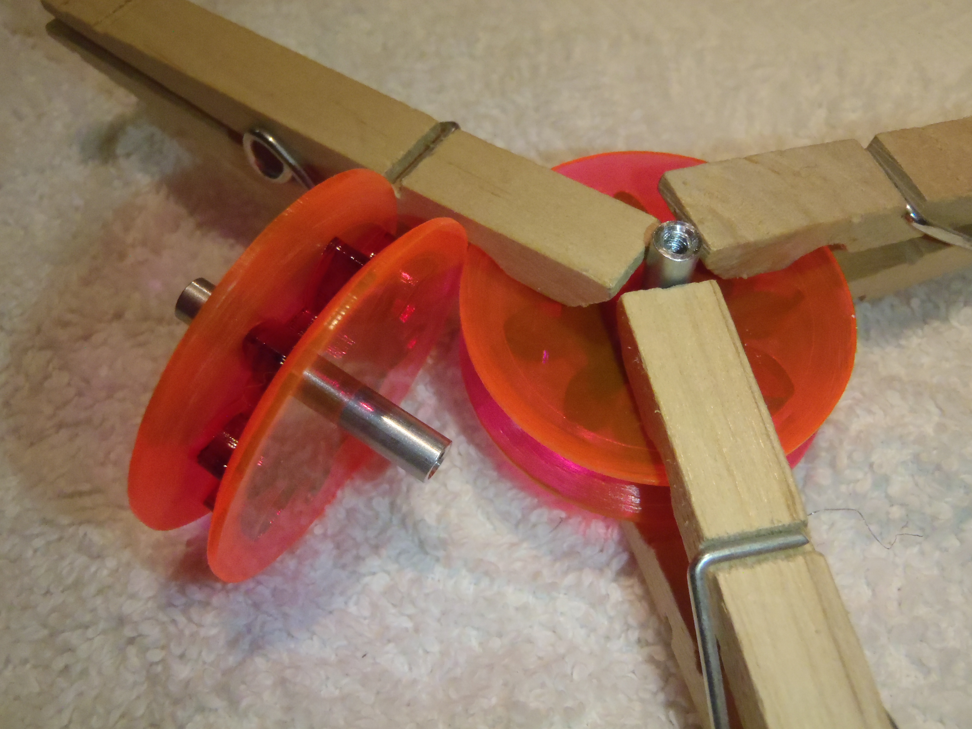
Note the placement of screws and washers in the crank-arm assembly.
Roughen a washer to be epoxied between the crank-arm and the
main drive axle.
Note the placement of screws and washers in the crank-arm assembly.
 Nearly fill the countersink with epoxy.
You may want to put a smaller amount of epoxy in the countersink,
but put a very small dab of epoxy on both sides of the flat weasher, near the screw hole.
(As you install the crank arm, this epoxy will spread to form the bond.)
Nearly fill the countersink with epoxy.
You may want to put a smaller amount of epoxy in the countersink,
but put a very small dab of epoxy on both sides of the flat weasher, near the screw hole.
(As you install the crank arm, this epoxy will spread to form the bond.)
Insert the flat-head screw through the crankarm so that it will fit intimately inside the countersunk hole. Then install the flat washer over the screw, then thread the screw into the main axle standoff.
Since this is primarily a glue joint you do not want to tighten the screw. Just thread it until the fit is snug, and not loose.
 Very carefully repeat the procedure in the previous step, but being very
careful to align this second crankarm to be exactly opposite of the first crankarm.
Very carefully repeat the procedure in the previous step, but being very
careful to align this second crankarm to be exactly opposite of the first crankarm.
Repeat from step 7) for the other main-bar assembly.
|
Note that the current photograph is from an assembly that did not work.
The motor and gear must be mounted and in-place before you epoxy
the crank-arms to the main drive axle standoffs.
It is intended to show cemented parallel, opposed, crank-arms, but should be replaced with a photo that shows this with the motor gear assembly in-place. |
Allow the epoxy to set.
 Last modified: Mon Nov 25 10:13:49 MST 2013