Blue protective film was left on clear cranklinks to
enhnce their visibility in photographs.
Film should be removed in your assembly.
Note that lock washers should NEVER touch the acrylic.
They are only used between screw-heads or nuts and washers.
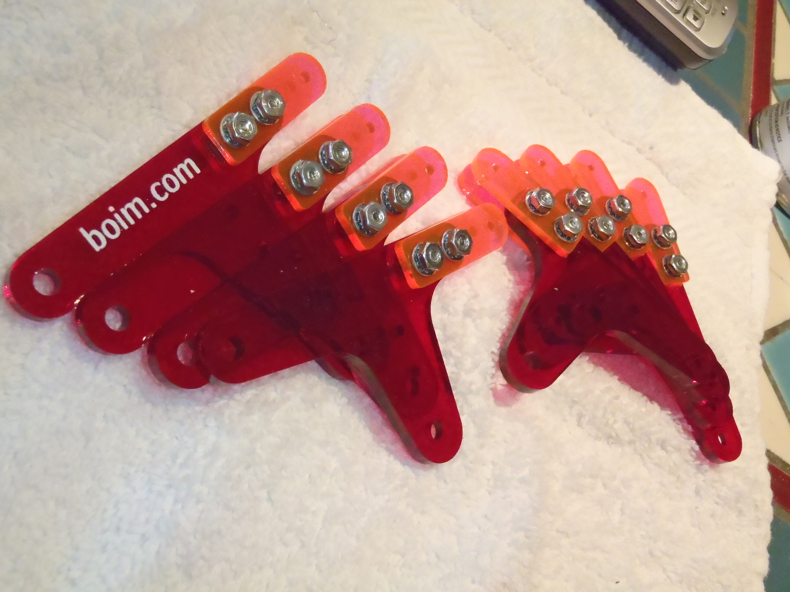
1)
Pre-assemble the EF links
Attach three of the short standoffs to each of 8 of the EF-links using
a 1/4" screw, internal tooth lock washer, and washer, in that order.
Torque enough to engage the lock-washers, but no more.
Too much torque on these screws can crack the acrylic.
It is better to re-tighten screws that have worked loose later than to
damage the plastic.
2)
BED sub-assemblies
D-forks
For the BED assemblies on a right leg, (as you look at legs on top of a main bar), place the thin stacker on top of the BED piece.
For legs which will be on the left, place the thin stacker on the side which will be below the BED piece.
Install one side of the D-fork.
If you place the BED assembly on a table, with the B-axle fork up, and pointing down (towards you), the holes for the fork tab could be on the left or the right.
holes to the right
Place a thin stacker (0.5mm) below the BED assembly D-alignment holes
holes to the left
Place a thin stacker (0.5mm) on top of the BED assembly D-alignment holes
Place a pair of D-forks on either side of the assembly, and attach
with finger-tightened 5/8" screw/internal-tooth-lock-washer/washer/BED+stacker/washer/lock-washer/washer/nut assemblies.
Repeat the above procedure to create 4 left-handed and 4 right handed BED pieces with D-forks.
B-forks
Complete left and right-handed BED sub-assemblies
Place one 2mm stacker and one 3mm stacker between the wide-holed B-axle
fork and a BED "T" piece.
Secure with 3/4" screw, internal-tooth lock-washer and washer below the screw head.
Insert the screw through the alignment holes, then attach with a washer,
lock-washer, then nut.
Finger tighten.
Repeat the above procedure to create 4 left-handed and 4 right handed BED sub-assemblies.
Some builders may wish to cement the B-forks in place.
The screws and nuts can be used as alighment clamps when applying the cement.
It is recommended to apply the cement while the B-fork is mounted on
and axle to assure proper alignment.
Note that screws should be snug, but not tight when using an Acrylic cement.
If the nuts are tightened, even finger-tight, it may cause stress-fractures
in acrylic softened with solvent.
3)
Attach BED(hip) cranklinks
Using a short (3/16") standoff/spacer, install one of the shorter (CD) cranklinks into the BED D-fork with 2-3 nylon washers.
For left-handed T-links (where the D-fork is toward the right when
the B-fork is facing you and pointed down),
the washers should be on top of the link.
For the right-haded T-links, the washers should be under the link.
Secure the standoff in place using two 1/4" screws, followed by an internal-tooth lockwasher and washer.
Torque these screws lightly, enough to engage the lockwashers, but not
so tight that it cracks the plastic.
Friction between the standoff and the plastic should hold the standoff
in place as you torque the screw to engage the lockwasher.
If the pieces do spin, you can torque both screws simultaneously to
install the D-hinge standoff.
(Or secure with a spacer, snug but not tight, with a screw,
2 washers, and locknut)
Torque the nuts attaching the D-forks to the BED(hip)-T piece after the
standoff has been installed, and you have checked that the cranklink
moves freely.
The lockwashers on the opposite side should hold the screwheads in place as you torque the nut, or vica-versa if you prefer to torque with a screwdriver.
Repeat this procedure for all 4 left-hand BED sub-assemblies,
and 4 right-hand BED sub-assemblies.
4)
H-forks on feet
Using (2) 3/4" screws, (4) lock-washers, (4) washers, and
(2) nuts, attach wide-hole forks to the foot piece
using one 2mm and one 3mm stacker (or two 0.100" stackers).
Build 4 left-handed and 4 right-handed feet with H-forks.
H-forks can be glued instead of screwed if desired.
Screws can be used as clamps to cement these forks (With Weld-On #3, #4, or Acetone).
Screws should be snug, but not tight to clamp, or the plastic may crack when
using solvent-type cements.
5)
Blue protective film was left on clear CH crank-links so that they are easier to see in this photograph
Complete H-node hinge attachments
For left-hand feet, place the longer CH link sich that it touches the
man foot piece, with spacers to fill the rest of the gap up to
the H-fork.
For right-handed feet, let the CH link contact the H-fork, with spacers
to fill the gap down to the main foot piece.
Place these pieces inside the foot-fork, and insert the tip
standoff from the BH-link through the holes from the foot-piece (NOT fork) side.
This assembly can be tricky, and is the most challenging step in
the construction of this walking linkage.
It is important that the extra BH brace be on the side of the main
foot piece, and not on the fork-tyne side of the H-node.
Stock thickness can vary.
If the standoff is significantly longer than the H-fork assembly,
extra space can be reduced with a nylon washer.
Attach the other side-plate for the BH-link to the H-node with a
3/8" screw, lock-washer and washer.
Secure this side plate with another
3/8" screw, lock-washer and washer in the middle standoff.
This side of the BH-link does not have the extra brace.
Repeat this assembly to complete 4 left-hand feet, and 4 right-hand feet.
6)
Complete leg assemblies
Use the EF-link with the three standoffs attached to link the
E-node of the BED sub-assembly with the wide F-node on the
foot sub-assembly.
Secure this link with the other EF-link side plate using
5/16" screws, internal-tooth-lockwasher and washer screwed into the
short standoffs.
Repeat this procedure to form 4 sets of left-hand legs, and
4 sets of right-hand legs.
Blue film was left on cranklinks to make parts easier to see
in photographs.


 Using a short (3/16") standoff/spacer, install one of the shorter (CD) cranklinks into the BED D-fork with 2-3 nylon washers.
For left-handed T-links (where the D-fork is toward the right when
the B-fork is facing you and pointed down),
the washers should be on top of the link.
For the right-haded T-links, the washers should be under the link.
Using a short (3/16") standoff/spacer, install one of the shorter (CD) cranklinks into the BED D-fork with 2-3 nylon washers.
For left-handed T-links (where the D-fork is toward the right when
the B-fork is facing you and pointed down),
the washers should be on top of the link.
For the right-haded T-links, the washers should be under the link.