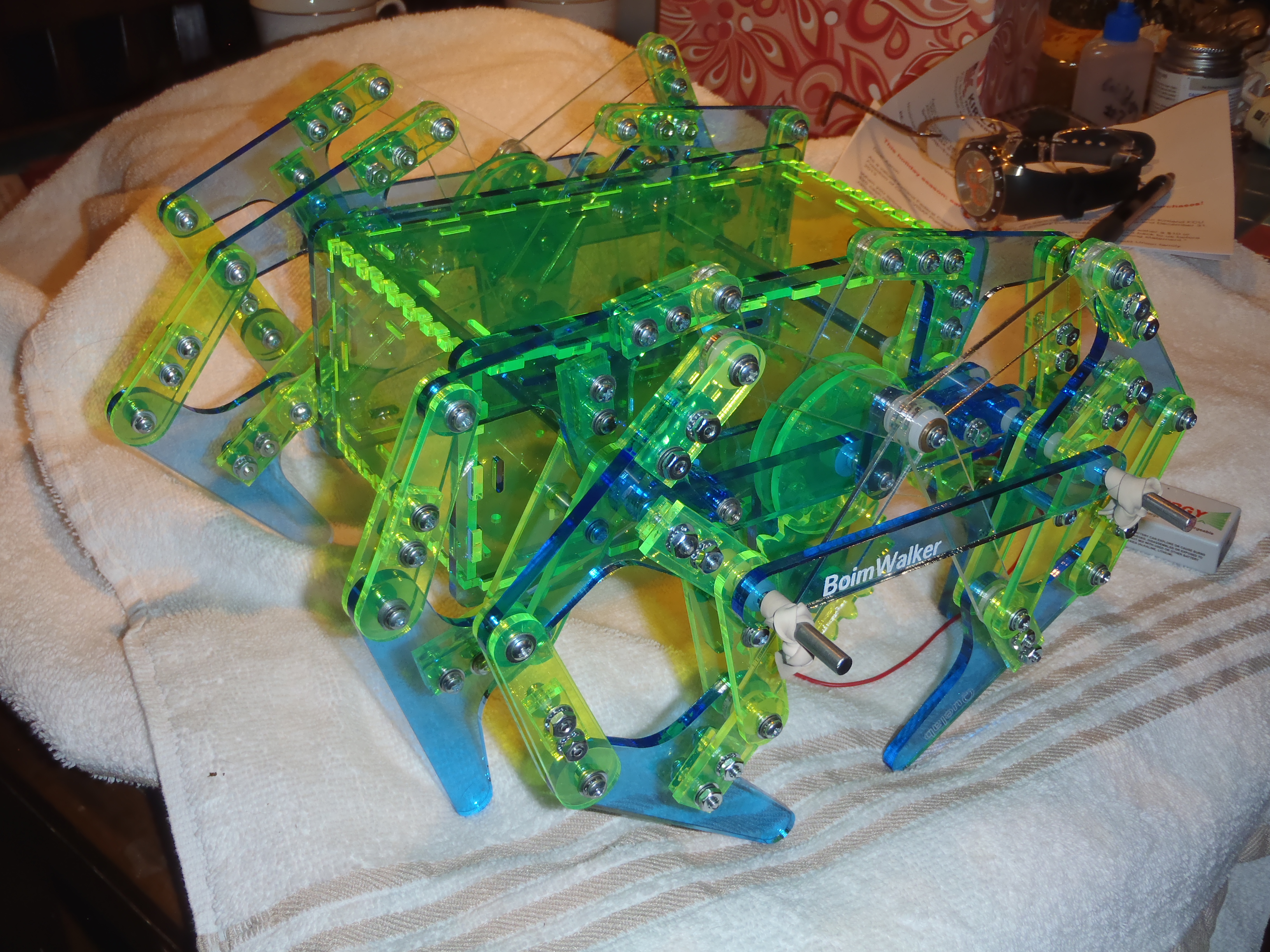


|
Expendible materials:
| 2 | 3/16" OD hard steel rod, 12" in length | |
|---|---|---|
84 | #10-32 nuts #10 lockwashers | |
| 8 | 1/2" long, 3/16" OD #4-40 round female-female standoffs | |
| 2 | 1/2" long, #4-40 threaded rods.
May be constructed by cutting the head off of a #4-40 screw, and cleaning the threads. | |
| 4 | #4-40 flat-head screws, 3/8" long | |
| 6 | #4ish self-piloting plastic screws, 1/4" long | |
| 32 | #4-40 screws, 1/2" long. | 4 spindles 3*8 hinges 4 motor driver mount |
| 12 | #4-40 screws, 7/8" long. | 4 motor mounts 8 hinges |
| 4 | #4-40 screws, 1 1/8" long. (main bar) | |
| 4 | #4-40 screws, 1/4" long. (spindles) | |
| 8 | #4-40 nuts
Can use these while cementing parts |
Main bar and motor mounts |
| 36 | #4-40 nyloc nuts | 4*8 hinges 4 motor driver mount |
| 16 | #4 internal tooth lockwashers | 4 motor mounts 4 main bar 8 spindles (both sides) |
| 14 | larger diameter #4 washers | 2 motor gears 4*2 on spindles 4 under crank-arm |
| 90 | #4 washers | 2*4*8 hinges 4 on spindles 8 motor mount 8 main bar 6 lid tabs |
| 12 | 1/4" long, 3/16" ID nylon spacers | on B-axle to space out legs |
| 8 | 1/2" long, 3/16" OD #4 nylon spacers | hinges |
| 36 | 3/16" long, 3/16" OD #4 nylon spacers | 3*8 hinges 8 hip-B fillers 4 motor driver mount |
| 72 | 3/16" ID nylon washers (#10), around 1mm thick | ~3*8 spindles ~16 B-axle 2*2*8 hinges |
Main assembly parts:
For Uno-based Bluetooth remote control electronics:
Welding is unnecessary for most of this project, simply an asthetic decision. However, welding the main drive gear to it's guidance plates should make the gear teeth a little stronger, which might be a good idea.
It may not be necessary to epoxy the motor gear to the shaft, but it should certainly make that connection stronger, and perhaps longer-lived.
These are still being re-written from the previous build configuration. This text should be augmented with illustrated, detailed step instruction pages as they become available
Note that there will be 4 left-handed, and 4 right-handed hip and foot pieces.
When the forks are installed "on top" of the foot/hip piece,
half should face one direction, and the other half should face the other direction.
After the wide forks have been installed, install the narrow hip forks in a similar fashion. The hip-D attachment will have two forks tynes, instead of one fork tyne on top of stackers. If your 4.5mm stock is actually thinner than 4.4mm, you may want to cement a thin PETG shim under one of the fork tynes. I recommend installing the shim UNDER each left-hand hip, and ON TOP of each right-hand hip. (Which one is "left" and "right" is not critical, just that you maintain symetry)
We are now using a screw with a nylon spacer, 2 flat washers, and a nylock for each hinge
instead of a standoff, two screws, two flat washers and two lock washers.
I am no longer recommending the additional braces on EF or BH. (Unnecessary weight and complexity)
Nylon spacer hinges should have snug, but not tight nyloc nuts. I usually tighten them until I feel some resistance, then back off 1/4 turn.
Install 3 braces on each side of the main bar with 1 1/8" screws with
a flat washer below the head.
Then install the main gear axle onto the motor-mount side of the main bar,
on the same side as these braces (opposite side of motor clip).
Install the other side of the main bar onto these screws,
and secure loosely with a washer, lockwasher, and nut.
Slide the motor and gear assembly into place from the bottom.
Place the crescent motor brace and back clip around the motor holding it into place.
Rotate the motor gear until the hole is over the un-secured side of the motor fork.
Install the other screw and washer by passing them through this hole.
Plase 2 more spacers behind the crescent motor brace, then secure the back side of the
motor clip onto the screw with a washer, lockwasher, and nut.
A screwdriver may be used to brace this screw as the nut is tightened.
Move the hole to lay over the other screw, brace it, and tighten the other nut.
Make sure the brace holes are alighed to cover the axle hole, and tighten these screws.
Roughen the crank-arm inside the counter sink, and near the hole on the other side. Apply some epoxy (JB-Weld) and screw this crank-arm to the main gear axle snugly.
Repeat for the other side, making sure that the crank arms are exactly opposing each other (180 degrees apart), and allow to set.
|
|
|
|
| XD | Xerocraft layout, linkage configuration D |
|---|---|
| 20 | scaled for 20mm crank arms |
| 22 30 45 | Layout for 2.2, 3.0, 4.5mm acrylic respectively |
| XXXxYYY | Scale of rectangle containing drawing, in mm |
This scale in the filename is for a rectangle containing the outside tips of the corner fiducials.
This should make it easier to import the drawings, just set the scale of the imported object
to the size referenced in the file name.
The spacing from center to center of the fiducials is actually 1mm less than the numbers in the file name.
 Last modified: 131007